
Integrated DC/DC converter substrate connections

a technology of dc/dc converter and substrate, applied in the field of dc/dc power conversion integration, can solve the problems of destroying such fine line structures, creating new and unique problems when combining these components within an individual integrated circui

Active Publication Date: 2008-05-06
KINETIC TECH INT HLDG LP
View PDF1 Cites 45 Cited by
  • Summary
  • Abstract
  • Description
  • Claims
  • Application Information

AI Technical Summary

Problems solved by technology

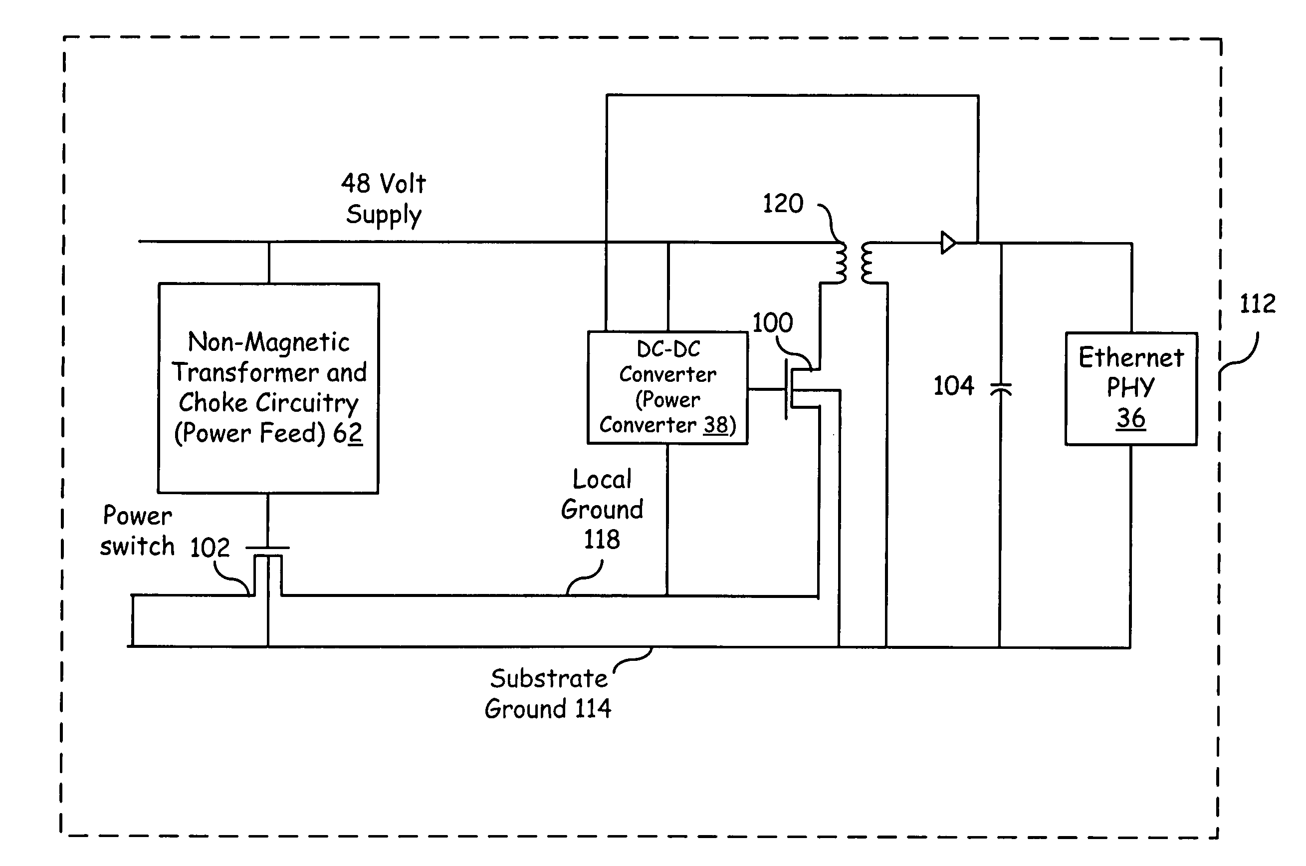
Unlike prior solutions where these individual components may be implemented on a board or as discreet components where each component may be individually grounded, combining these components within an individual integrated circuit creates new and unique problems.
In such a case, the Ethernet PHY and its fine line structures may be exposed to a 48 volt differential which could potentially destroy such fine line structures.

Method used


Image

  • Integrated DC/DC converter substrate connections
  • Integrated DC/DC converter substrate connections
  • Integrated DC/DC converter substrate connections

Examples


Embodiment Construction

[0027]Preferred embodiments of the present invention are illustrated in the FIGS., like numerals being used to refer to like and corresponding parts of the various drawings.

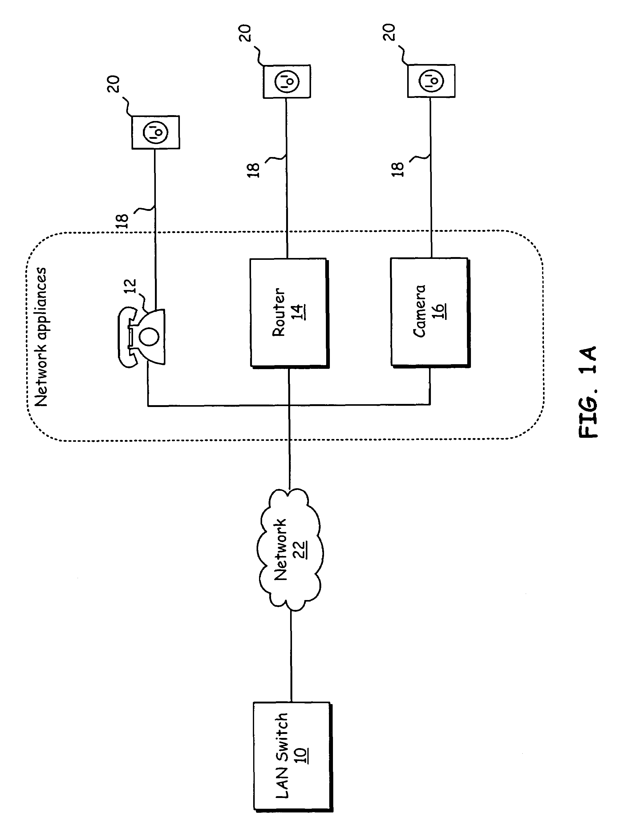
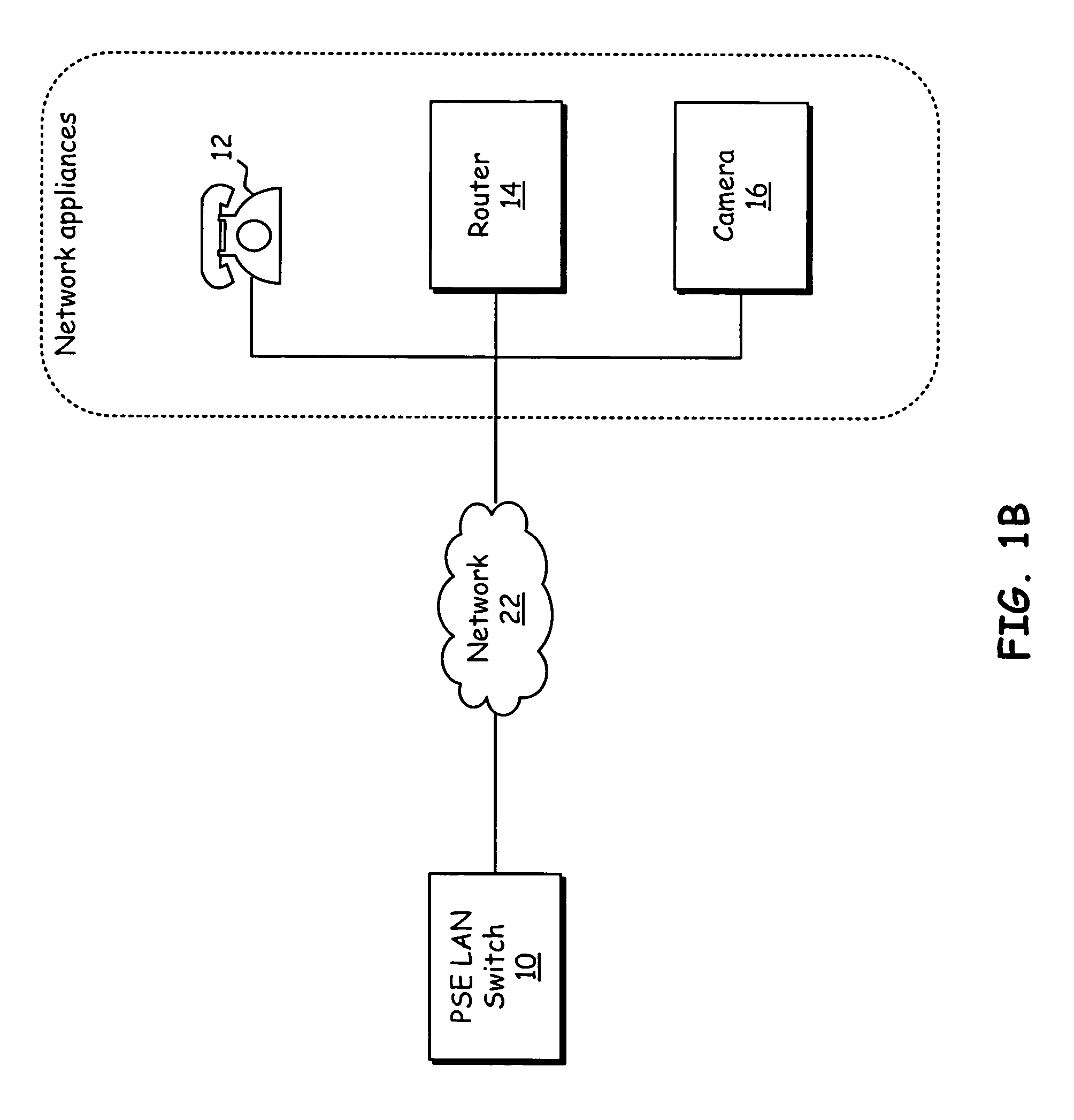
[0028]The 802.3 Ethernet Standards, which is incorporated herein by reference, allow loop powering of remote Ethernet devices (802.3af). The Power over Ethernet (PoE) standard and other like standards intends to standardize the delivery of power over Ethernet network cables in order to have remote client devices powered through the network connection. The side of link that supplies the power is referred to as Powered Supply Equipment (PSE). The side of link that receives the power is referred to as the Powered device (PD).

[0029]Replacing the magnetic transformer of prior systems while maintaining the functionality of the transformer has been subsumed into the embodiments of the present invention. In order to subsume the functionality of the transformer, the circuits provided by embodiments of the present inventio...


PUM


Abstract

Embodiments of the present invention provide an integrated circuit (IC) having an integrated DC-DC power converter therein. This IC is operable to support the distribution of combined power and data signals in a network environment such as an Ethernet network according to protocols such as the power over Ethernet (PoE) protocol. The IC includes a DC-DC power converter, a power feed circuit, and a network physical layer (PHY) module, wherein the PHY module may contain fine line structures susceptible to damage when exposed to excessive voltages. To prevent or reduce the likelihood of damage to the PHY module from voltages supplied to the DC-DC power converter, a common substrate ground is shared between the IC components.

Description

CROSS REFERENCE TO RELATED APPLICATIONS[0001]This application claims the benefit of priority to and incorporates herein by reference in its entirety for all purposes, U.S. Provisional Patent Application No. 60 / 665,766 entitled “SYSTEMS AND METHODS OPERABLE TO ALLOW LOOP POWERING OF NETWORKED DEVICES,” by John R. Camagna, et al. filed on Mar. 28, 2005. This application is related to and incorporates herein by reference in its entirety for all purposes, U.S. patent application Ser. No. 11 / 207,595 entitled “METHOD FOR HIGH VOLTAGE POWER FEED ON DIFFERENTIAL CABLE PAIRS,” by John R. Camagna, et al. filed Aug. 19, 2005; and U.S Pat. Ser. No. 11 / 207,602 entitled “A METHOD FOR DYNAMIC INSERTION LOSS CONTROL FOR 10 / 100 / 1000 MHZ ETHERNET SIGNALLING,” by John R. Camagna, et al., filed Aug. 19, 2005.TECHNICAL FIELD OF THE INVENTION[0002]The present invention relates generally to the integration of DC / DC power conversion within power over Ethernet devices.BACKGROUND OF THE INVENTION[0003]Many n...

Claims


Application Information

Patent Timeline
Patent Type & Authority Patents(United States)
IPC IPC(8): H01L29/00
CPCG06F1/266Y10S370/91
Inventor CAMAGNA, JOHN R.GHOSHAL, SAJOL
Owner KINETIC TECH INT HLDG LP
Learn More