
Adaptive crash structure for a vehicle body or chassis of a motor vehicle

a technology for motor vehicles and crash structures, applied in vehicle bodies, monocoque structures, understructures, etc., can solve the problems of self-locking and clamping action of telescopic wedge bodies

Inactive Publication Date: 2008-04-15
BENTELER AUTOMOBILTECHNIK GMBH
View PDF7 Cites 66 Cited by
  • Summary
  • Abstract
  • Description
  • Claims
  • Application Information

AI Technical Summary

Benefits of technology

The present invention is an adaptive crash structure for a vehicle body or chassis of a motor vehicle that includes a deformation element. The deformation element is made up of a first metal casting, a second metal casting, and a deformation element in the form of a plurality of funnel-shaped wedge bodies. The deformation element is formed in one piece with the metal castings, reducing the number of parts and the complexity of the structure. The deformation element is designed to absorb energy and convert crash energy into deformation energy. The wedge bodies are designed to come into contact with each other and clamp together in a self-locking manner, preventing separation during a crash. The deformation element can be positioned at an angle to the length direction of the vehicle, and the neighboring wedge bodies can have wall portions that come into contact with each other to improve self-locking. The deformation element is retained in its entirety through a casting process, reducing weight and improving crash behavior. The invention provides an efficient and effective solution for absorbing crash energy in a motor vehicle.

Problems solved by technology

Once, a limit stress is encountered, the predetermined breaking webs rupture to allow the wedge bodies to move into one another, ultimately causing a clamping action and self-locking of the telescoping wedge bodies.

Method used


Image

  • Adaptive crash structure for a vehicle body or chassis of a motor vehicle
  • Adaptive crash structure for a vehicle body or chassis of a motor vehicle
  • Adaptive crash structure for a vehicle body or chassis of a motor vehicle

Examples


Embodiment Construction

[0026]Throughout all the Figures, same or corresponding elements are generally indicated by same reference numerals. These depicted embodiments are to be understood as illustrative of the invention and not as limiting in any way. It should also be understood that the drawings are not necessarily to scale and that the embodiments are sometimes illustrated by graphic symbols, phantom lines, diagrammatic representations and fragmentary views. In certain instances, details which are not necessary for an understanding of the present invention or which render other details difficult to perceive may have been omitted.

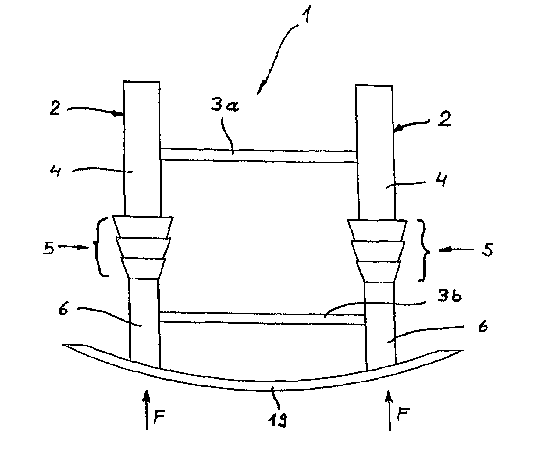
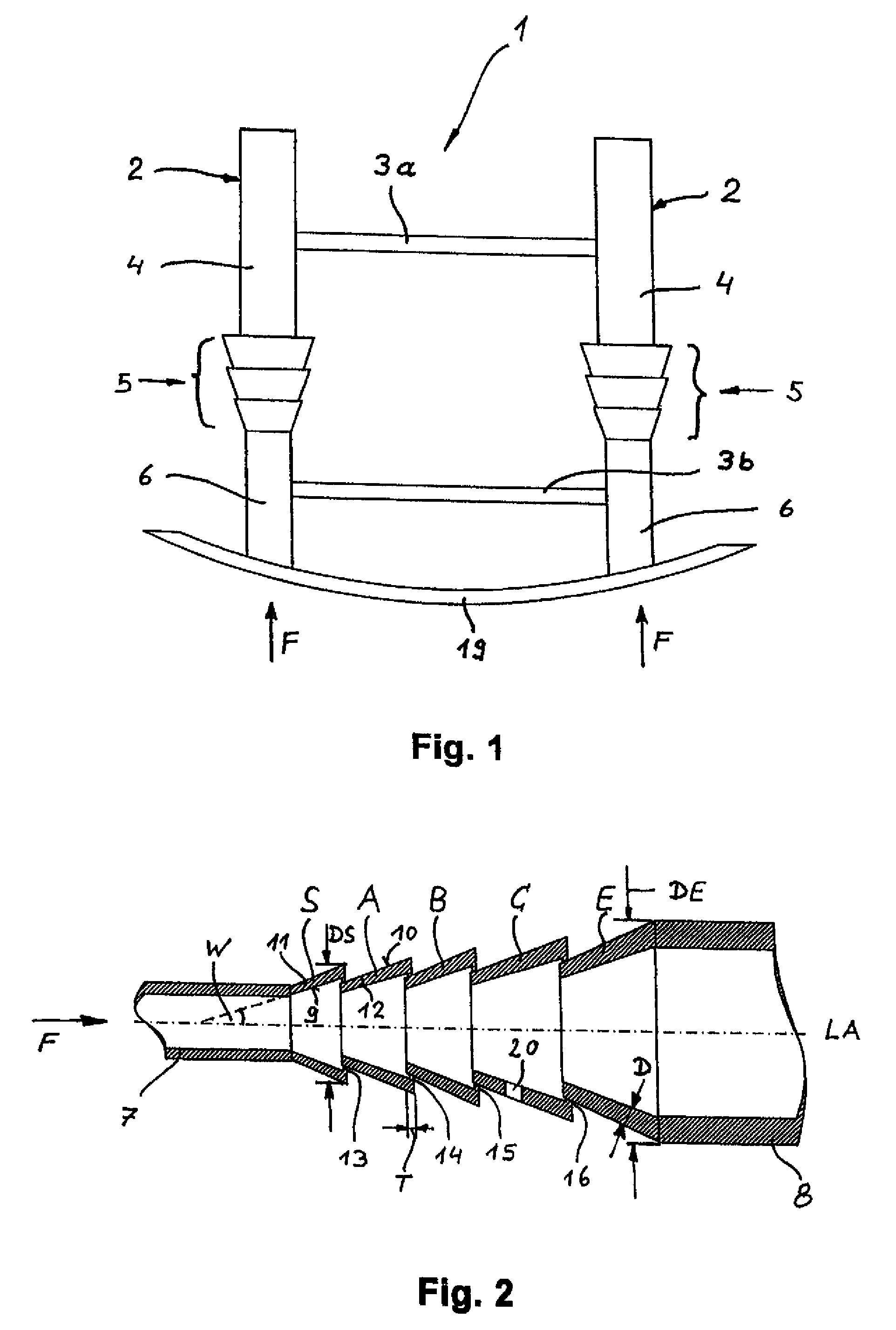
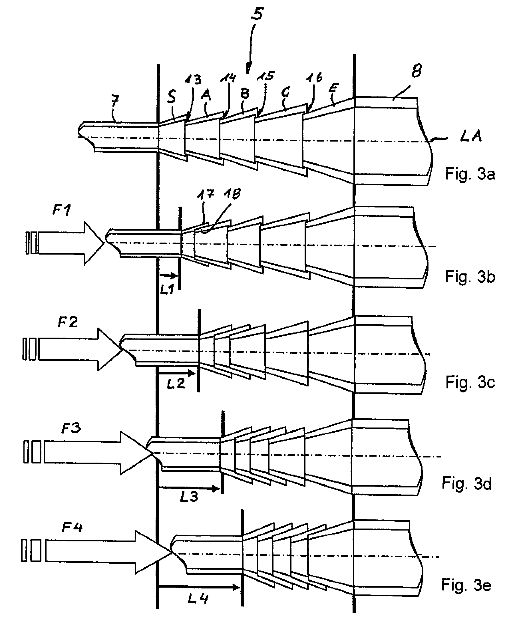
[0027]Turning now to the drawing, and in particular to FIG. 1, there is shown a simplified schematic plan view of an adaptive crash structure according to the present invention, generally designated by reference numeral 1, for use in a motor vehicle. The structure 1 includes two side parts 2 which extend in travel direction of the vehicle, and two crossbars 3a, 3b which extend...


PUM


Abstract

An adaptive crash structure of a vehicle body or chassis of a motor vehicle includes a first metal casting and a second metal casting. A deformation element in the form of a metal casting for absorbing energy interconnects and forms with the first and second metal castings a single piece construction through a casting process. The deformation element is comprised of a plurality of funnel-shaped wedge bodies which are disposed in succession, with neighboring wedge bodies being connected through intervention of a predetermined breaking web. Each wedge body is defined by a diameter, wherein the diameters of the wedge bodies are sized to allow the wedge bodies to move telescopically into one another when a limit stress is reached and the predetermined breaking webs rupture so as to effect a tight intergrip of the telescoping wedge bodies in a self-locking manner.

Description

CROSS-REFERENCES TO RELATED APPLICATIONS[0001]This application claims the priority of German Patent Application, Serial No. 10 2005 041 021.9, filed Aug. 29, 2005, pursuant to 35 U.S.C. 119(a)-(d), the content of which is incorporated herein by reference.BACKGROUND OF THE INVENTION[0002]The present invention relates to an adaptive crash structure for a vehicle body or chassis of a motor vehicle.[0003]Nothing in the following discussion of the state of the art is to be construed as an admission of prior art.[0004]Heretofore, complex metal castings have been used in front or rear zones of a motor vehicle, in particular when crash structures and chassis parts are involved. Employing castings of aluminum, aluminum alloys or other suitable cast materials result in weight saving while still allowing realization of complex structures. In order to meet the demand for resilience in the event of impact, relatively thick-walled and rigid castings have been combined to date with thin-walled def...

Claims


Application Information

Patent Timeline
Patent Type & Authority Patents(United States)
IPC IPC(8): B60R19/34
CPCB62D21/152F16F7/125B60R19/34
Inventor GROSS, WALTERSTOLLE, JENSNEUMANN, HANS-JURGENSTREUBEL, WOLFGANG
Owner BENTELER AUTOMOBILTECHNIK GMBH
Learn More