
Methods for monitoring and controlling boiler flames

a technology for monitoring and controlling boiler flames, applied in lighting and heating apparatus, instruments, nuclear elements, etc., can solve problems such as x /sub>and inefficient boiler control

Inactive Publication Date: 2008-04-01
ELECTRIC POWER RES INST INC
View PDF37 Cites 21 Cited by
  • Summary
  • Abstract
  • Description
  • Claims
  • Application Information

AI Technical Summary

Benefits of technology

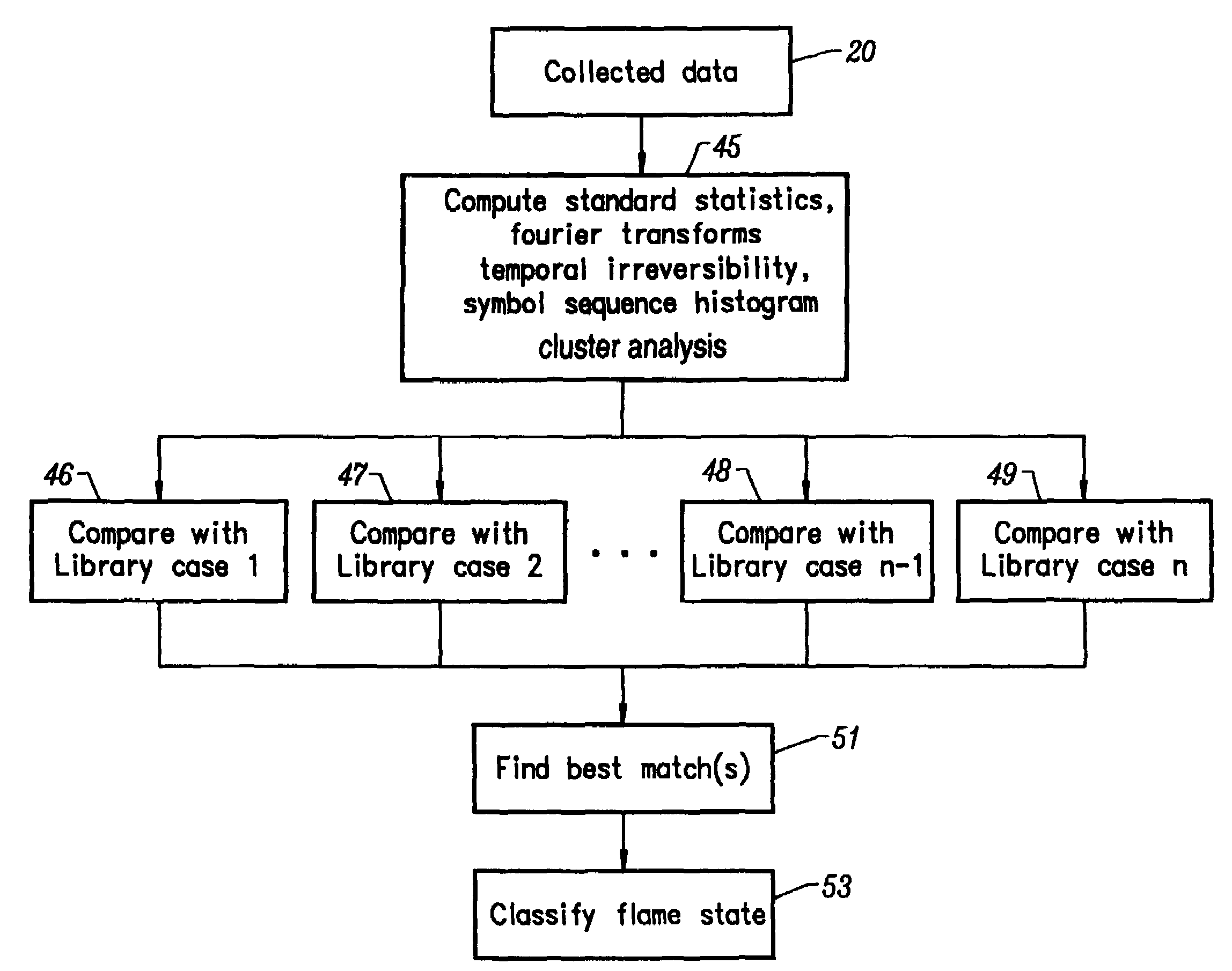
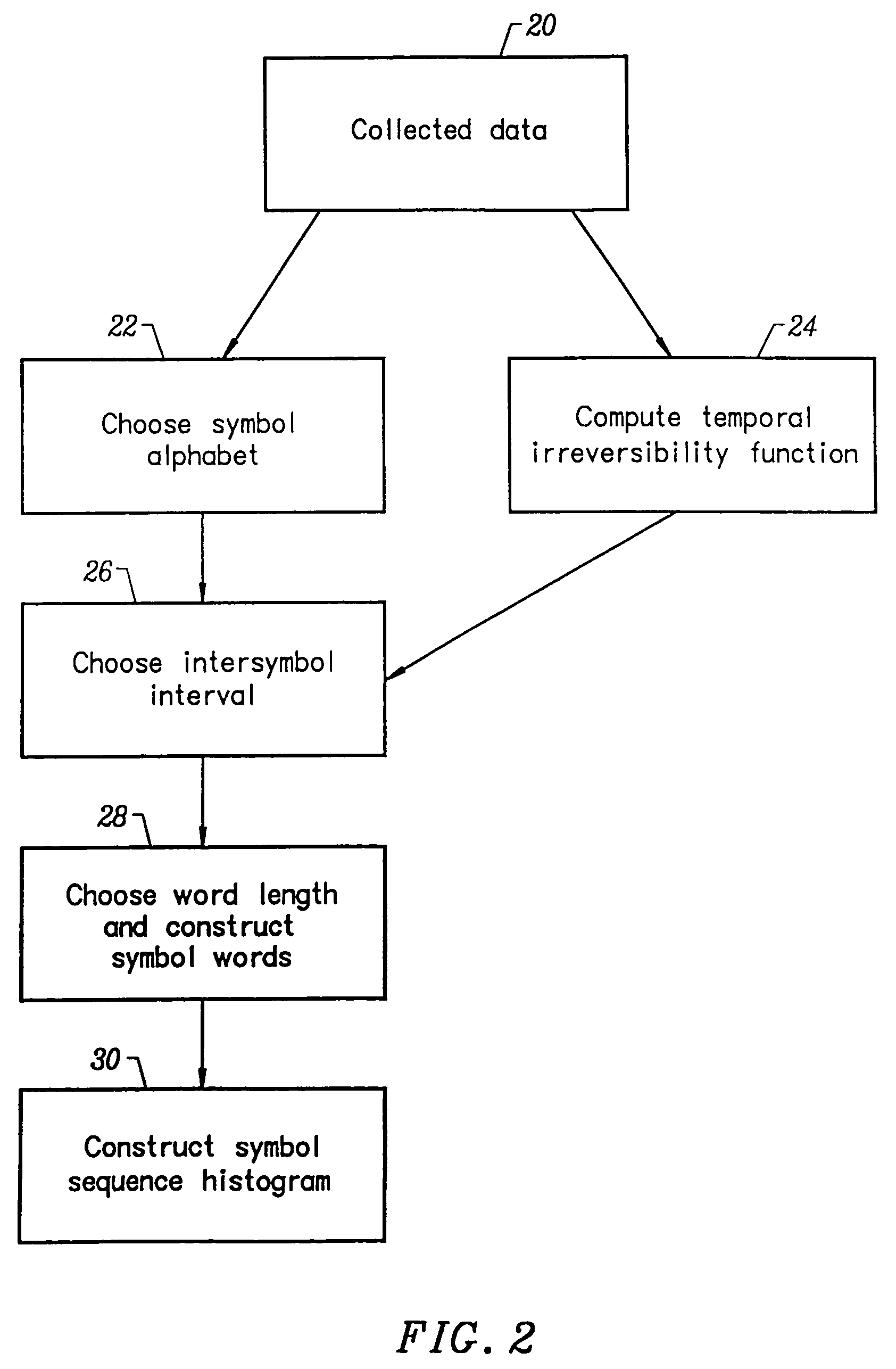
The present invention provides a method and apparatus for monitoring the operating state of burner flames using symbol sequence techniques, temporal irreversibility methods, and cluster analysis. The invention can be used to optimize the performance of burner flames and identify root causes of non-optimal flames. The invention can be used with various types of burners, such as low-NOx coal flames and oil flames. The sensor data can be obtained using optical scanners, infrared scanners, pressure transducers, or acoustical sensors. The invention can also convert the operating state of the burner flame to a sequence symbol histogram for further analysis. Overall, the invention provides a more effective and efficient way to monitor and optimize the performance of burner flames.

Problems solved by technology

Inefficient boiler control is responsible for wasting large amounts of fuel heating value and releasing nitrogen oxide pollutants into the atmosphere.
However, large NOx and carbon burnout fluctuations can occur in individual burners over short time scales (i.e., between about 10 seconds to fractions of a second).
The A / F ratio also affects slagging, fouling and corrosion phenomena that typically occur in the combustion zone.
Unfortunately, in multiburner, steam generator furnaces the A / F ratio differs from burner to burner and accordingly may vary significantly with burner location.
Since both combustion efficiency and NOx generation levels depend on the localized values of the A / F ratio (i.e., the distribution and mixing within each flame), measurement and control of the global A / F ratio produced by the entire furnace of the steam generator does not necessarily optimize performance.
In coal-fired burners, the complexity of the process is further increased by the presence of both solids and volatile components in the fuel, which mix and burn at characteristically different rates.
Although the dynamics of coal-fired burners are complex, certain global bifurcations in flame structure typically occur.
Primary zone combustion becomes unstable and flickers on and off in repeated ignition and extinction events, when conditions in the primary zone are too rich or the flow velocity is too high.
External perturbations to the burner (e.g., air or fuel flow disturbances) may cause transitions between these two states.
Extinction of combustion in the primary zone can also occur if there is an excessive amount of oxygen present.
This can happen in coal-fired burners when the release of volatile matter from the fuel is too slow to keep the gas mixture above the lean flammability limit.
Whether caused by high air velocity or excessively rich or lean primary zone conditions, lifted flames are an undesirable operating condition typically associated with excessive emissions of pollutants.
Bifurcations and associated flame front shifting can also occur in the radial direction due to excessively high or low rates of mixing between primary and secondary zones.
In some cases, flame size may also undergo large expansion and contraction.
Like axial flame shifting, radial flame shifts are associated with excessive emissions of pollutants and reduced fuel utilization.
Larger or smaller flame diameters are usually detrimental to performance.
Conventional analysis methods such as Fourier analysis and univariate statistics are based on assumptions that are not entirely valid for burners.
Chaos theory (especially, symbol sequence techniques and temporal irreversibility) avoids the assumptions of conventional analytical methods and thus may provide information unavailable from these well-known techniques.

Method used


Image

  • Methods for monitoring and controlling boiler flames
  • Methods for monitoring and controlling boiler flames
  • Methods for monitoring and controlling boiler flames

Examples


example

[0131]The following example is offered solely for the purpose of illustrating features of the present invention and is not intended to limit the scope of the present invention in any way.

[0132]Data was acquired at McDermott Technology Incorporated's (Alliance, Ohio) Clean Environment Development Facility (“CEDF”) in Alliance, Ohio. The CEDF is designed to test a single 100-Mbtu (30-MWt) burner at near commercial scale. Flow patterns, temperatures, residence times and geometry are representative of a middle row burner in a commercial utility boiler. All measurements were made using one of two eastern bitiminous coals.

[0133]FIG. 5 illustrates an overall profile view of the CEDF. A side view of the CEDF is illustrated in 50. Here, 52 is a burner, while 54 is the furnace exit. Sight and access ports are located for example at 56. A front view of the CEDF is illustrated in 58. FIG. 6 shows a schematic view of the CEDF that illustrates the approximate location of optical, acoustical and p...


PUM


Abstract

The current invention provides a method and apparatus, which uses symbol sequence techniques, temporal irreversibility, and / or cluster analysis to monitor the operating state of individual burner flames on a appropriate time scale. Both the method and apparatus of the present invention may be used optimize the performance of burner flames.

Description

[0001]This application is a continuation-in-part of U.S. patent application Ser. No. 10 / 438,156, filed May 13, 2003, now U.S. Pat. No. 6,901,351, which is a continuation-in-part of U.S. patent application Ser. No. 10 / 004,000, filed Nov. 14, 2001, now U.S. Pat. No. 6,775,645. U.S. patent application Ser. Nos. 10 / 438,156 and 10 / 004,000 and U.S. Pat. Nos. 6,775,645 and 6,901,351 are each incorporated by reference herein in their entireties.FIELD OF THE INVENTION[0002]The present invention relates, in general, to methods and apparatus for boiler flame diagnostics and control. More particularly, the present invention provides methods and apparatus for monitoring the operating state of burner flames using temporal irreversibility and symbol sequence techniques.DESCRIPTION OF THE RELATED ART[0003]Economic pressures and increasingly restrictive environmental regulations have contributed to an increasing need for advanced management systems that efficiently regulate utility boilers. Ineffici...

Claims


Application Information

Patent Timeline
Patent Type & Authority Patents(United States)
IPC IPC(8): G06F19/00G06F17/40
CPCF23M11/045F23N5/08F23N5/16F23N2023/44F23N2029/04F23N2029/08F23N2223/44F23N2229/04F23N2229/08
Inventor DAW, CHARLES STUARTFULLER, TIMOTHY A.FLYNN, THOMAS J.FINNEY, CHARLES E. A.
Owner ELECTRIC POWER RES INST INC
Learn More