Control device for non-positive connections

a control device and non-positive technology, applied in the direction of screws, load-modified fasteners, instruments, etc., can solve the problems of reversible elongation of the screw shaft, no information about the state of the screw connection, and the loss of the function of the connection

Inactive Publication Date: 2008-04-01
FRAUNHOFER GESELLSCHAFT ZUR FOERDERUNG DER ANGEWANDTEN FORSCHUNG EV
View PDF20 Cites 14 Cited by
  • Summary
  • Abstract
  • Description
  • Claims
  • Application Information

AI Technical Summary

Benefits of technology

[0023]A common embodiment provides that the measuring element has a core onto which the force sensory coating is applied. The core is preferably made from hardened or unhardened steel or alloyed steels or stainless steel or from ceramic materials or from glass-fibre reinforced plastics etc. To prevent brittle fractures in the coating it is, however, useful in the case of diamond-like carbon compounds in the force sensory layer not to provide core materials which are too readily deformable, eg lead. In principle the core can even be produced from materials having a low melting point since in the case of use of force-sensitive diamond-like carbon layers the layer can also be applied by cold methods (preferably below 150 degrees centigrade).
[0025]The device according to the invention can additionally contain electric connections and an electric circuit for obtaining, transmitting and evaluating signals. To prevent problems due to ingress of liquid or the ability of individual elements to rotate transmission of signal values can also ensue by telemetry.

Problems solved by technology

This force results in a reversible elongation of the shaft of the screw and presses the components to be joined against one another in non-positive manner.
These connections can lose their function due to vibration, settlement processes or the like.
All these methods, however, provide no information about the state of a screw connection and are intended to maintain a status quo which has already set in.
These methods yield only unreliable results and are highly dependent, for example, on the coefficient of friction between the screw head and the underlying material which changes markedly with operating time.
On the one hand, it is not suitable for every shape of head and, on the other hand, a new characteristic curve must be recorded for every type of screw.
Furthermore, due to the high cost of the ultrasonic read-out continuous monitoring of many screw connections is hardly economically achievable.
These solutions, however, have the disadvantage that a relatively great deformation and hence measuring distance must be used as may be seen in DE 198 31 372 with reference to FIG. 1b or 1c.
A great disadvantage of the known solutions also consists in that there can be no optimized adjustment of the axial force measurement.
Consequently, with high loads the sensitivity of the measurement falls since the gradient of the curves turns out to be considerably flatter.
This gives rise to high costs for measurements, which may still be inaccurate.

Method used


Image

  • Control device for non-positive connections
  • Control device for non-positive connections
  • Control device for non-positive connections

Examples


Embodiment Construction

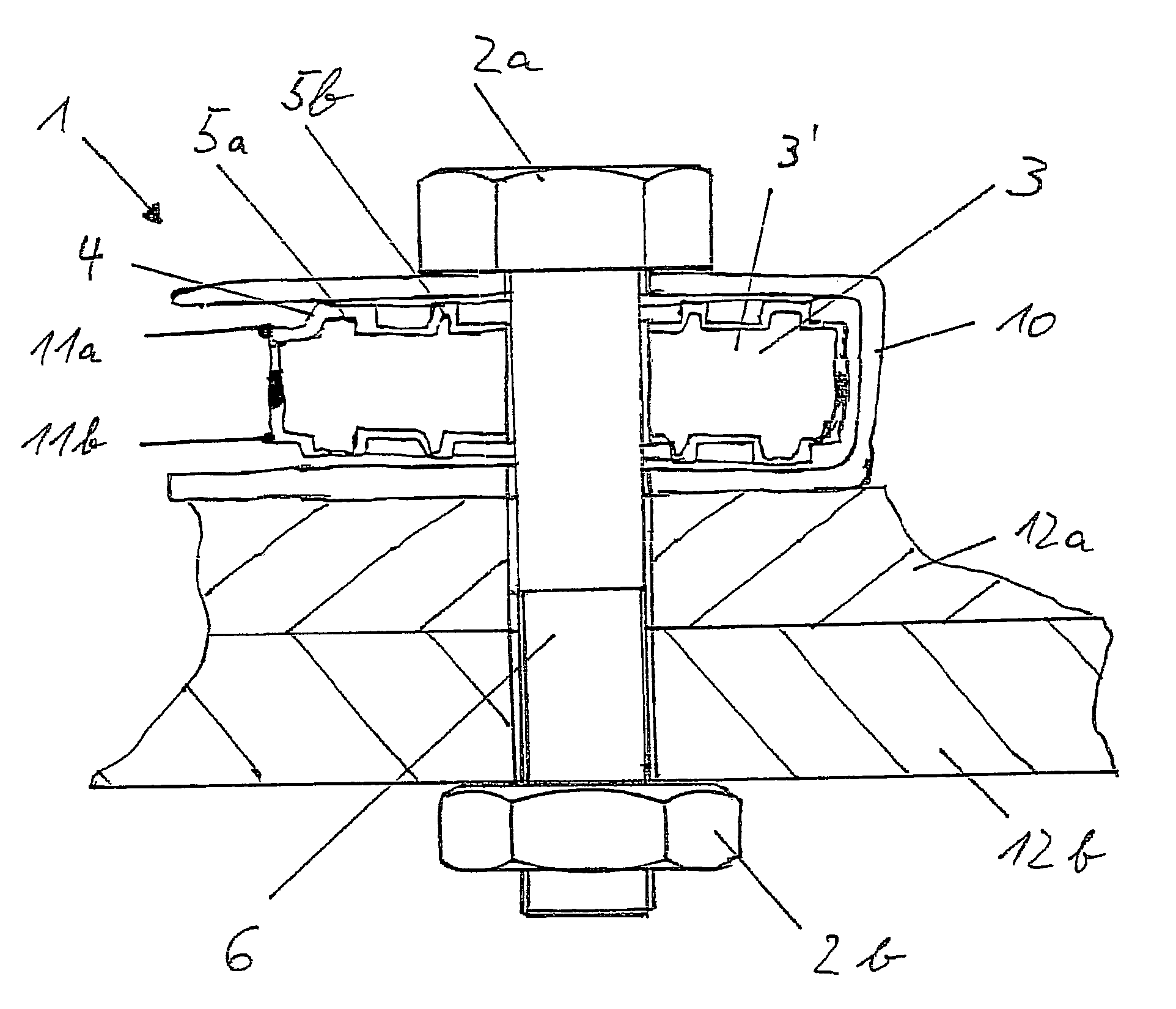
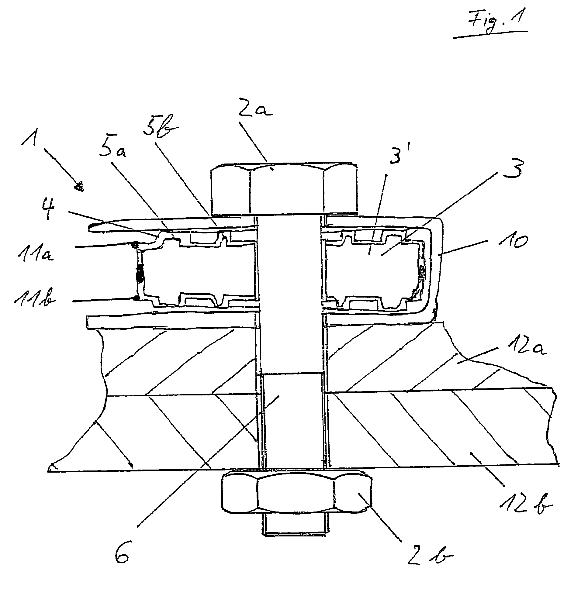
[0032]FIG. 1 shows a device 1 for checking non-positive connections. A screw connection is shown. A screw shaft 6 has a screw head 2a rigidly connected thereto at its upper end and a nut 2b screwed on by means of a thread at its lower end. The screw head 2a and nut 2b are two force-application elements as defined by the invention.

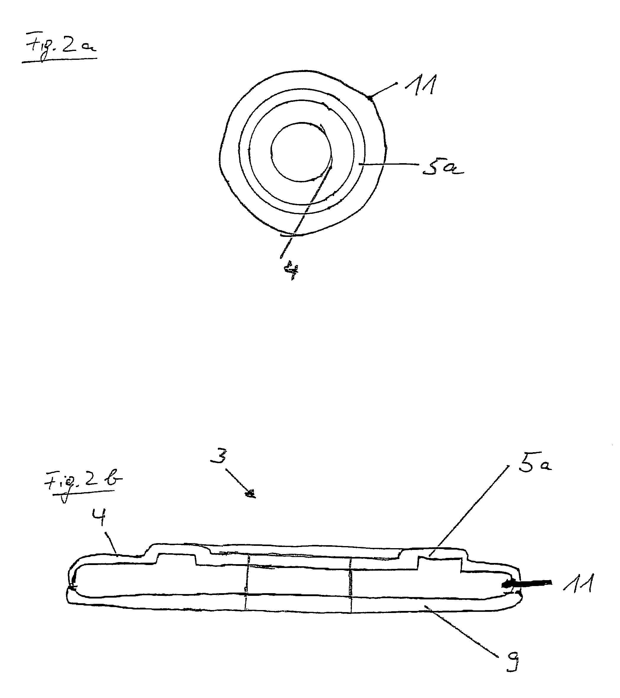
[0033]Fitted between these force-application elements are two structural elements 12a and 12b to be joined in non-positive manner which have corresponding openings for the screw shaft 6 to pass through. Provided on the upper structural element 12a is a measuring element 3 according to the invention inside a sleeve 10. The measuring element 3 is covered substantially over its entire surface by a layer 4. Fitted on the upper and on the lower side of the measuring element 3 are concentric annular prominences 5a (outside) and 5b (inside) which are concentric with a central bore for the screw shaft to pass through. The prominences project from the upper and lowe...


PUM

PropertyMeasurementUnit
melting pointaaaaaaaaaa
electrical resistanceaaaaaaaaaa
forceaaaaaaaaaa

Abstract

The invention relates to a control device for non-positive connections, especially screw connections. The device includes two force application elements and a measuring element arranged therebetween. The measuring element is at least partially provided with a layer having a force sensory effect. The surface of the layer is provided with elevations for receiving a force applied by the force application elements.

Description

[0001]This application is a 371 of PCT / EP03 / 03750.BACKGROUND OF THE INVENTION[0002]The invention relates to a control device for non-positive connections, advantageously screw connections.[0003]Screw connections are based on the conversion of a torque into an axial force via a thread. This force results in a reversible elongation of the shaft of the screw and presses the components to be joined against one another in non-positive manner. Screw connections are numbered among the detachable connections in the construction industry, wherein their greatest danger is also found. These connections can lose their function due to vibration, settlement processes or the like.[0004]To prevent independent detachment various methods are employed. Split pins can be fitted transversely through the screw to prevent it falling out. But then the joint has in reality already been loosened. Various types of adhesives are further used which are intended to prevent loosening due to vibration. Furthermore...

Claims


Application Information

Patent Timeline
Patent Type & Authority Patents(United States)
IPC IPC(8): F16B31/02G01L5/00G01L5/24
CPCF16B31/028G01L5/243
Inventor LUTHJE, HOLGERBIEHL, SASKIABANDORF, RALF
Owner FRAUNHOFER GESELLSCHAFT ZUR FOERDERUNG DER ANGEWANDTEN FORSCHUNG EV
Why Eureka
Try Eureka