Eureka AIR delivers breakthrough ideas for toughest innovation challenges, trusted by R&D personnel around the world.

High-temperature component for a turbomachine, and a turbomachine

a technology of high-temperature components and turbomachines, which is applied in the direction of machines/engines, liquid fuel engines, other chemical processes, etc., can solve the problems of material fatigue, shortened service life, and shortened service life of blades and vanes, so as to reduce vibration, reduce load, and protect blades and vanes. the effect of high temperatur

Inactive Publication Date: 2008-03-25
SIEMENS AG
View PDF4 Cites 28 Cited by
  • Summary
  • Abstract
  • Description
  • Claims
  • Application Information

AI Technical Summary

Benefits of technology

[0005]Therefore, the invention is based on the object of providing a high-temperature component which is protected against torsional and flexural loads in a particularly simple way. Furthermore, a turbomachine of particularly simple design is also to be provided.
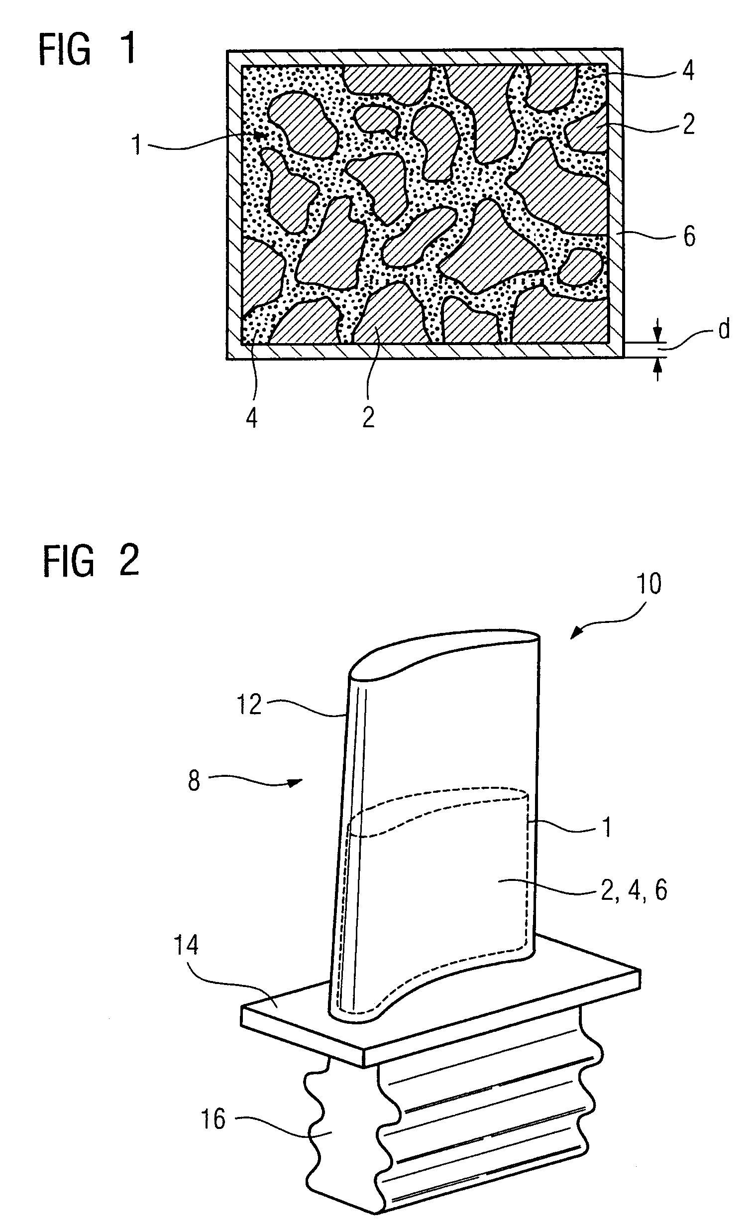
[0008]In this context, the invention is based on the consideration that a high-temperature component which is exposed to high thermal, torsional and flexural loads should be able to make do without complex damping elements for reducing the levels of vibrations. Therefore, the high-temperature component itself should be of suitable design to achieve this purpose. To this end, it is provided that the high-temperature component be formed at least in part, and in particular in the regions which are subject to high levels of vibrational loading, as base material, from a porous material which is filled with a viscous filler and is surrounded by a solid layer. The porous material has the advantage of being particularly thermally stable and resistant to high temperatures. Furthermore, it is distinguished by a high resistance to corrosion, oxidation and other chemicals, such as combustion gases. Suitable selection of the viscous filler moreover makes the high-temperature component particularly mechanically strong and sufficiently resistant to stresses and damping. In the event of mechanical loading of the high-temperature component, e.g. resulting from vibrational movements, a relative movement takes place between the porous material and the fluid filler. The friction which is produced causes damping and therefore a reduction in vibrations and also a reduction in stresses.
[0009]It is expedient for the porous material used to be a raw material based on silicon dioxide, a raw material based on aluminum oxide, a raw material based on zirconium oxide, a raw material based on magnesium oxide or a raw material based on mica and aluminosilicates. The material may also be based on silicon carbide or aluminum titanate or another material with a carbide or nitride structure or metal materials. These raw materials are distinguished by a high thermal stability and resistance to high temperatures and to fluctuating thermal loads. Moreover, these raw materials are particularly resistant to corrosion and oxidization.
[0012]It is expedient for the viscous filler used to be a fluid, in particular a heat-resistant fluid. By way of example, the viscous filler used is a lubricant, in particular a polyalkylene glycol, a synthetic hydrocarbon, a dicarboxylic acid and polyol ester, a silicone, a polyphenyl ether, a fluorohydrocarbon. Furthermore, it is possible to use a phosphate. The synthetic hydrocarbon used may, for example, be poly-alpha-olefins, diakyl benzenes, polyisobutylenes. Viscous fillers of this type are distinguished by a high thermal stability, resistance to oxidation, high-pressure stability and viscosity-temperature properties. Alternatively, the viscous filler used may also be a wax material or a liquid metal filling.
[0015]It is expedient for the solid layer of the high-temperature component to have a thickness of from 100 μm to 1000 μm, in particular from 180 μm to 300 μm or from 200 μm to 500 μm, in order to provide sufficient protection against corrosion and wear.
[0018]The advantages achieved by the invention consist in particular in the fact that sufficient protection against mechanical loads caused by vibrations, e.g. flexural and torsional vibrations, is provided with a high-temperature component which at least in part as base material has a porous material which is filled with viscous filler. Furthermore, it is additionally possible to provide damping elements. The damping effected by the use of the porous material on account of the relative movement between the porous material and the viscous filler leads to a reduction in vibrations and therefore to a reduction in the load on the high-temperature component caused by mechanical stresses, so that the service life of the high-temperature component is extended.

Problems solved by technology

In addition to thermal loads of this type, the blades and vanes are in particular also exposed to high mechanical loads, e.g. vibrations.
When the turbomachine is operating, various operating states can cause flexural and torsional vibrations, in particular at the transition region from the blade or vane root to the main blade or vane part, which can lead to material fatigue and therefore to a shortened service life.

Method used


Image

  • High-temperature component for a turbomachine, and a turbomachine
  • High-temperature component for a turbomachine, and a turbomachine
  • High-temperature component for a turbomachine, and a turbomachine

Examples


Embodiment Construction

[0023]Parts which correspond to one another are provided with identical reference symbols throughout the figures.

[0024]FIG. 1 shows a base material 1 which is formed from a porous material 2. The porous material 2 is filled with a viscous filler 4 and surrounded by a solid layer 6.

[0025]The porous material 2 used is, for example, a raw material based on silicon dioxide, a raw material based on aluminum oxide, a raw material based on zirconium oxide, a raw material based on magnesium oxide, a raw material based on aluminum titanate, a raw material based on silicon carbide or a raw material based on mica and aluminosilicates. Depending on the specific stipulations, the porous material may have a porosity of at most 20%, in particular from 5% to 15% or from 10% to 15%. The porous material 2 may also have a porosity which varies, e.g. from 10%, 20% to at most 30%, or a variable pore size, e.g. a mean pore size of from 20 μm to 80 μm, in particular from 20 μm to 40 μm or 40 μm to 60 μm.

[...


PUM

PropertyMeasurementUnit
porosityaaaaaaaaaa
porosityaaaaaaaaaa
thicknessaaaaaaaaaa

Abstract

The invention provides a high-temperature component for a turbomachine, in particular for a blade or vane having a main blade or vane part and a blade or vane root, the high-temperature component at least partially comprising, as base material, a porous material which is filled with a viscous filler and is surrounded by a solid layer.

Description

CROSS REFERENCE TO RELATED APPLICATION[0001]This application claims priority of the European application No. 04004021.4 EP filed Feb. 23, 2004, which is incorporated by reference herein in its entirety.FIELD OF THE INVENTION[0002]The invention relates to a high-temperature component, in particular a blade or vane having a main blade or vane part and a blade or vane root, for a turbomachine, e.g. for a gas turbine or a compressor. Furthermore, the invention relates to a turbomachine having a high-temperature component of this type.BACKGROUND OF THE INVENTION[0003]Conventional turbomachines, e.g. turbochargers, compressors, gas turbines, comprise high-temperature components, e.g. blades and vanes, such as guide vanes and rotor blades, carrier elements, ring elements, which are exposed to a high temperature and a corrosive or oxidative atmosphere produced by combustion gases. In addition to thermal loads of this type, the blades and vanes are in particular also exposed to high mechanic...

Claims


Application Information

Patent Timeline
Patent Type & Authority Patents(United States)
IPC IPC(8): F01D5/16F01D25/06F01D5/26F01D5/28F01D25/00
CPCF01D5/16F01D5/26F01D5/28F01D25/005F01D25/06F05C2201/0463F05C2201/0466F05D2300/43F05D2300/2102F05D2300/612F05D2300/615F05D2300/2118F05D2300/2112F05D2300/222Y10S416/50F05D2300/50
Inventor KAYSER, ANDREASWOLTER, IVO
Owner SIEMENS AG
Why Eureka
Eureka Blog
Learn More