
Dynamic-quantity sensor

a dynamic-quantity sensor and sensor technology, applied in the direction of generator/motor, acceleration measurement using interia force, instruments, etc., can solve the problems of difficult to reduce the size and cost of such a dynamic-quantity sensor, so as to improve the circuit configuration and reduce the size and cost

Active Publication Date: 2008-03-18
MURATA MFG CO LTD
View PDF13 Cites 2 Cited by
  • Summary
  • Abstract
  • Description
  • Claims
  • Application Information

AI Technical Summary

Benefits of technology

The present invention provides a dynamic-quant sensor with improved circuit configuration for dynamic-quant sensing that reduces the size and cost of the sensor as compared to previous versions. The sensor includes a piezoelectric-vibrator series circuit with two series-connected piezoelectric vibrators that are driven in series with each other. The sensor does not require an adder circuit or a differential amplifier circuit to control the oscillation frequency, reducing the size and power consumption of the sensor. The phase difference between the output portions of the amplifier circuit is adjusted by setting the capacitances of the two piezoelectric vibrators and the impedance of the output-side resistor, resulting in a wide dynamic range of changes in the phase difference in response to a dynamic quantity and preventing noise generation due to variations in the oscillation frequency. The sensor includes a series resistor in series with the first capacitor, which limits the sensitivity to a dynamic quantity but reduces the impact of variations in Qm on the sensitivity and aging.

Problems solved by technology

It is thus difficult to reduce the size and cost of such an acceleration sensor.
Similarly, the dynamic-quantity sensor in Patent Document 2 requires relatively large-scale circuits, such as the current-to-voltage-converting / signal adding circuit and the voltage-amplifying / amplitude-limiting circuit, for driving two piezoelectric vibrators in parallel with each other, and it is thus difficult to reduce the size and cost of such a dynamic-quantity sensor.

Method used


Image

  • Dynamic-quantity sensor
  • Dynamic-quantity sensor
  • Dynamic-quantity sensor

Examples


Embodiment Construction

[0032]With reference to FIGS. 1 to 4 and 10 to 12, the configuration of a dynamic-quantity sensor according to a first preferred embodiment will be described.

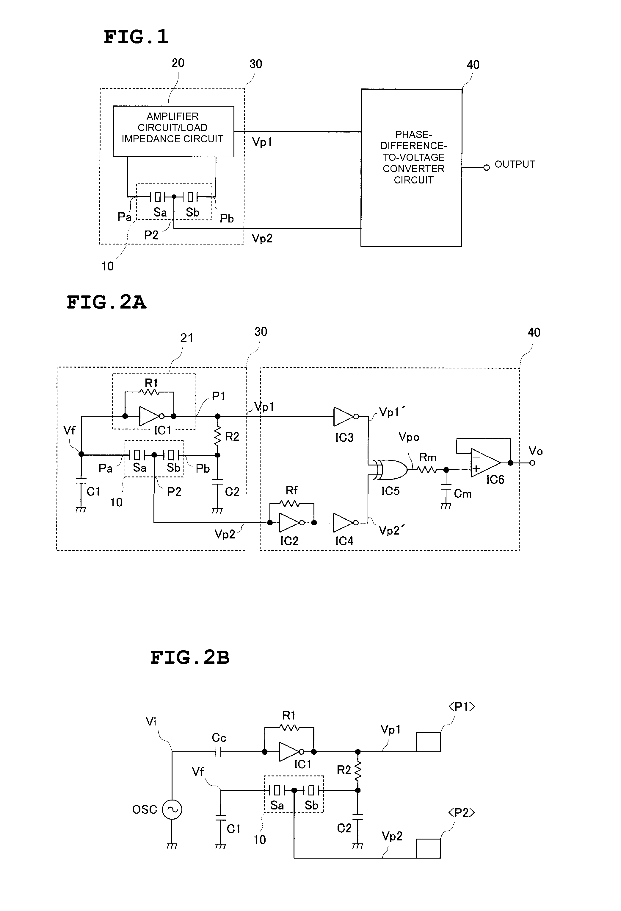
[0033]FIG. 1 is a block diagram of a dynamic-quantity sensor. Two piezoelectric vibrators Sa and Sb are disposed so that stresses induced by a dynamic quantity are applied thereto in opposite directions. These two piezoelectric vibrators Sa and Sb are connected in series to define a piezoelectric-vibrator series circuit 10. The piezoelectric-vibrator series circuit 10 and an amplifier circuit / load impedance circuit 20 define a Colpitts oscillator circuit 30. A phase-difference-to-voltage converter circuit 40 detects a voltage phase difference between voltages Vp1 and Vp2 output from the oscillator circuit 30 as a voltage signal, which serves as an output signal of the dynamic-quantity sensor.

[0034]FIGS. 2A and 2B include specific circuit diagrams of the dynamic-quantity sensor shown in FIG. 1. In the oscillator circuit 30, an a...


PUM

PropertyMeasurementUnit
phaseaaaaaaaaaa
voltageaaaaaaaaaa
output voltageaaaaaaaaaa

Abstract

A piezoelectric-vibrator series circuit including two series-connected piezoelectric vibrators to which stresses induced by a dynamic quantity are applied in opposite directions is used, and a Colpitts oscillator circuit is defined by the piezoelectric-vibrator series circuit and an amplifier circuit / load impedance circuit. A phase-difference-to-voltage converter circuit is provided to convert a phase difference between an output voltage of the oscillator circuit and a voltage at a piezoelectric-vibrator series node of the piezoelectric-vibrator series circuit into a voltage signal.

Description

BACKGROUND OF THE INVENTION[0001]1. Field of the Invention[0002]The present invention relates to a dynamic-quantity sensor for sensing a dynamic quantity, such as acceleration, angular acceleration, angular velocity, or load.[0003]2. Description of the Related Art[0004]The present applicant has filed Japanese Unexamined Patent Application Publication 2002-243757 (Patent Document 1) and Japanese Unexamined Patent Application Publication 2003-254991 (Patent Document 2) regarding a dynamic-quantity sensor with piezoelectric vibrators.[0005]The configuration of an acceleration sensor in Patent Document 1 is shown in FIG. 13 herein. As shown in FIG. 13, a bridge circuit 110 includes two piezoelectric vibrators S1 and S2 to which stresses induced by acceleration are applied in opposite directions, and capacitors C1 and C2. A voltage-dividing impedance circuit 120 is disposed between nodes p2 and p3. A signal at a voltage division point p5 of the voltage-dividing impedance circuit 120 is f...

Claims


Application Information

Patent Timeline
Patent Type & Authority Patents(United States)
IPC IPC(8): G01P15/09G01C19/00G01L1/16G01P15/10
CPCG01L1/162G01P15/09
Inventor YAMASHITA, MUNEHARU
Owner MURATA MFG CO LTD
Learn More