Apparatus and method for detecting beam power in optical drive
a technology of optical drive and apparatus, applied in the field of optical drive, can solve the problems of large optical drive, inability to realize an apc that consistently provides the light power required, and difficulty in ensuring a sufficient dynamic range for detecting the beam power generated by each light source, etc., and achieve the effect of sufficient dynamic rang
- Summary
- Abstract
- Description
- Claims
- Application Information
AI Technical Summary
Benefits of technology
Problems solved by technology
Method used
Image
Examples
first embodiment
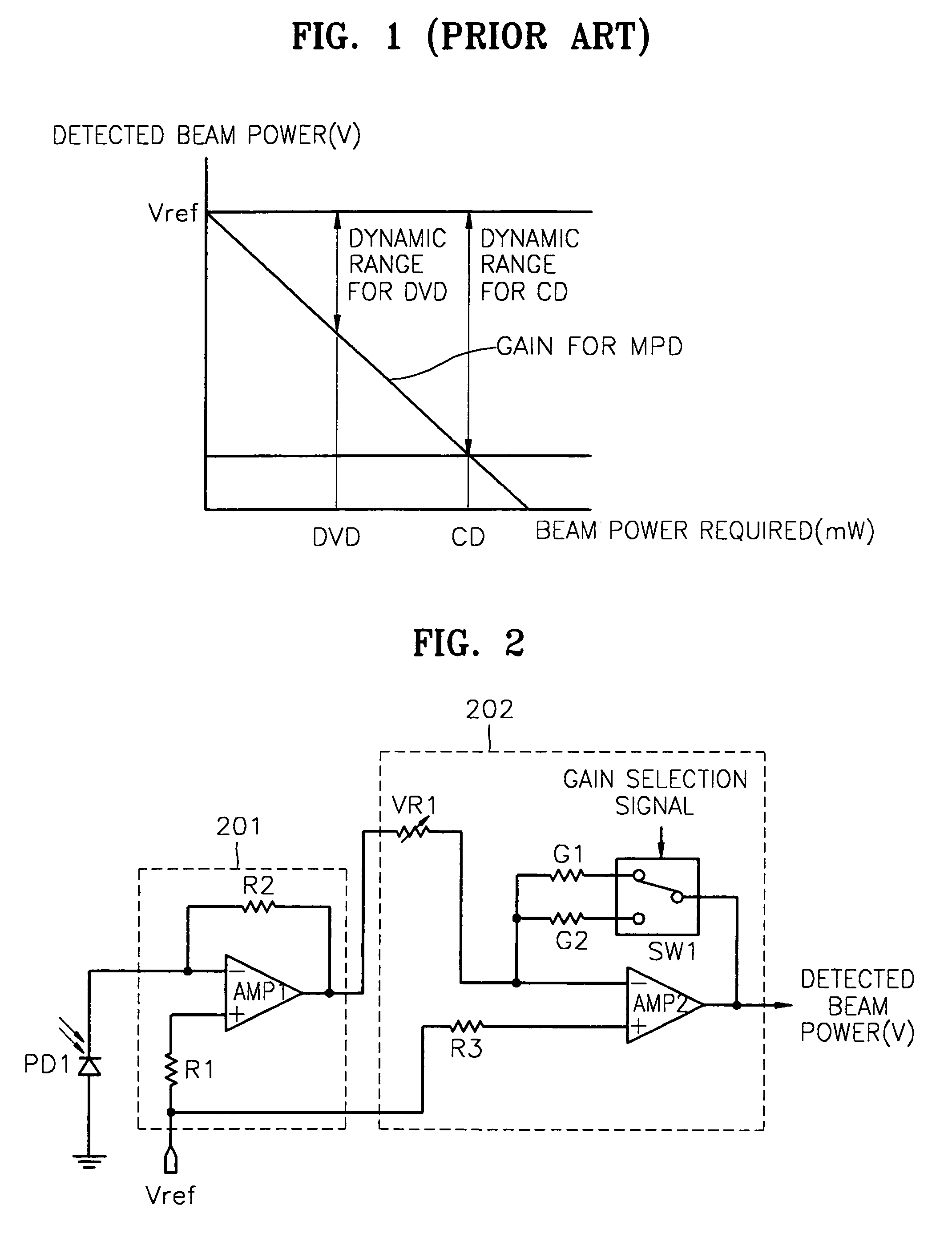
[0029]FIG. 2 is a diagram of a circuit for detecting the beam power in an optical drive according to the present invention. Referring to FIG. 2, the received beam power signal is amplified to a predetermined level according to a selected gain in response to a gain selection signal, and output as the detected beam power. The gain selection signal is generated based on the type of optical media present.
[0030]The circuit for detecting the beam power in an optical drive shown in FIG. 2 includes a photo diode PD1, a current-to-voltage amplifying unit (hereinafter, “I / V amplifying unit”) 201 and an amplifying unit 202. The photo diode PD1 functions as a light-receiving unit that receives light generated by one of a plurality of light sources (not shown) included in an optical drive. If the optical drive operates with both a disc classified as a CD and a disc classified as a DVD, the plurality of light sources include at least a light source for the CD and a light source for the DVD, with ...
second embodiment
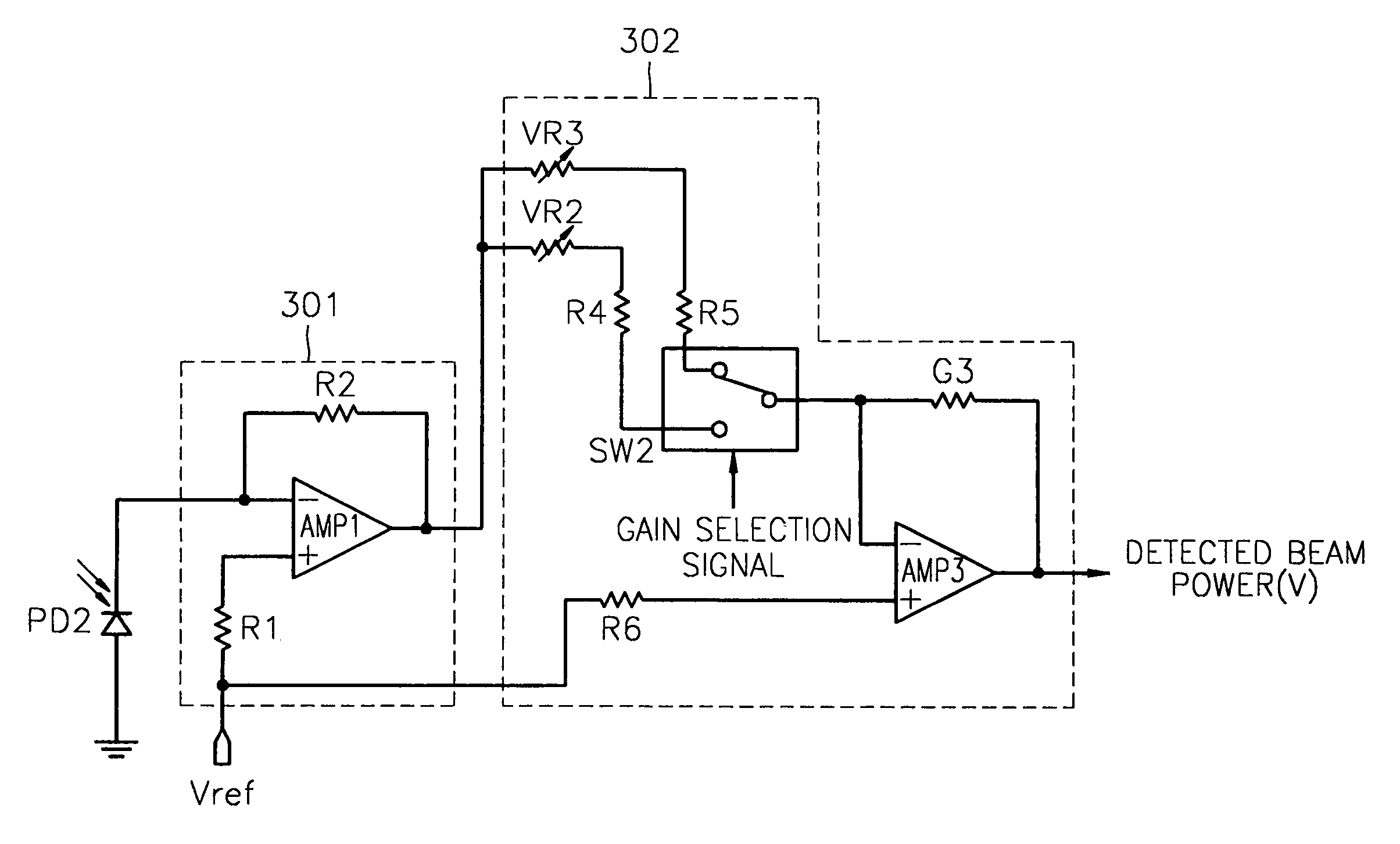
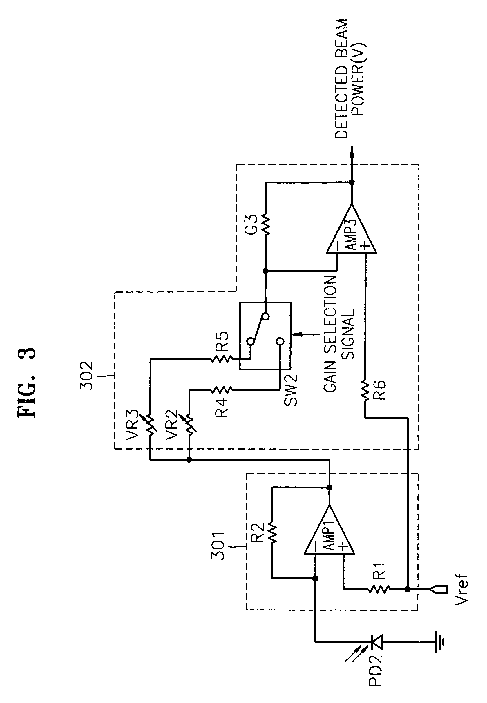
[0036]FIG. 3 is a diagram of a circuit for detecting the beam power in an optical drive according to the present invention. The circuit shown in FIG. 3 amplifies the beam power received according to a selected gain in response to a gain selection signal, which varies according to the type of optical medium used in the optical drive, and outputs the beam power amplified as the detected beam power. The circuit shown in FIG. 3 includes a photo diode PD2, an I / V amplifying unit 301 and an amplifying unit 302.
[0037]The structure and operations of the photo diode PD2 and the I / V amplifying unit 301 are the same as those of the photo diode PD1 and the I / V amplifying unit 201 of FIG. 2, and therefore, an explanation thereof will be omitted here.
[0038]The amplifying unit 302 includes an amplifier AMP3. In the amplifier AMP3, a bias resistance R6 is connected to an input terminal to which a reference voltage Vref is applied, and one feedback gain resistance G3 is connected to a feedback loop....
third embodiment
[0042]FIG. 4 is a diagram of a circuit for detecting the beam power in an optical drive according to the present invention. The circuit of FIG. 4 detects the beam power in an optical drive using a plurality of amplifying units that amplify light to a predetermined level according to a predetermined gain in consideration of a plurality of light sources, according to the type of an optical medium used in the optical drive.
[0043]The circuit of FIG. 4 includes a photo diode PD3, an I / V amplifying unit 401, first and second amplifying units 402 and 403, and a switch SW3.
[0044]The photo diode PD3 and the I / V amplifier 401 have the same structure and operations as the photo diode PD1 and the I / V amplifying unit 201, and therefore, an explanation thereof will be omitted here.
[0045]The first amplifying unit 402 includes an amplifier AMP4. In the amplifier AMP4, a bias resistance R7 is connected to an input terminal, to which a reference voltage Vref is applied, and a feedback gain resistance...
PUM
 Abstract
Description
Claims
Application Information
 - R&D
- Intellectual Property
- Life Sciences
- Materials
- Tech Scout
- Unparalleled Data Quality
- Higher Quality Content
- 60% Fewer Hallucinations
Browse by: Latest US Patents, China's latest patents, Technical Efficacy Thesaurus, Application Domain, Technology Topic, Popular Technical Reports.
© 2025 PatSnap. All rights reserved.Legal|Privacy policy|Modern Slavery Act Transparency Statement|Sitemap|About US| Contact US: help@patsnap.com


