Eureka AIR delivers breakthrough ideas for toughest innovation challenges, trusted by R&D personnel around the world.

Heater and heating device

a heating device and heater technology, applied in the field of heaters and heating devices, can solve the problems of affecting the reliability of the heater member, wasting energy, and affecting the heating arrangement of the hot plate, and achieve the effect of consuming less energy and high reliability

Inactive Publication Date: 2008-03-11
SUMITOMO ELECTRIC IND LTD
View PDF7 Cites 1 Cited by
  • Summary
  • Abstract
  • Description
  • Claims
  • Application Information

AI Technical Summary

Benefits of technology

The invention provides a to-be-placed-on-heat-subject heater member that is more efficient in heat application, reduces the amount of heat energy wasted, and prevents short-circuit accidents. The heater member has a low-radiation-rate film made of a material with lower radiation rate than the heater substrate, which results in a uniform temperature on the heat-subject-placing surface. The design flexibility of the heater member is also increased. The technical effects of the invention include improved heating efficiency, reduced energy waste, improved reliability, and increased design flexibility.

Problems solved by technology

As a result, the energy is often wastefully consumed, thereby being an obstacle to energy conservation.
Thus, increasing the application voltage leads to short-circuit accidents, whereby the reliability of the heater member is resultantly impaired.
As a result, the low-radiation-rate part showing low heat dissipation is increased in temperature with respect to the high-radiation-rate part showing high heat dissipation, and this temperature difference generates stress in the heater member resulting from the thermal expansion difference, thereby leading to the occurrence of possible breakage trouble of the heater member.
However, narrowing down the wiring width results in shorter life as a heating element, and having a closer wiring spacing results in lower insulation capability, and by extension, leads to short-circuit accidents.
Such subsidiary sections have been obstacles to achieving the uniform temperature on the heat-subject-placing surface, and moreover, have complicated pattern designing of the heat-generating wiring configuration to a greater degree, resultantly impairing the reliability and the heat uniformity of the heater member.

Method used


Image

  • Heater and heating device
  • Heater and heating device
  • Heater and heating device

Examples


Embodiment Construction

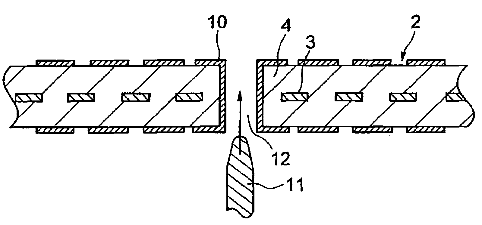
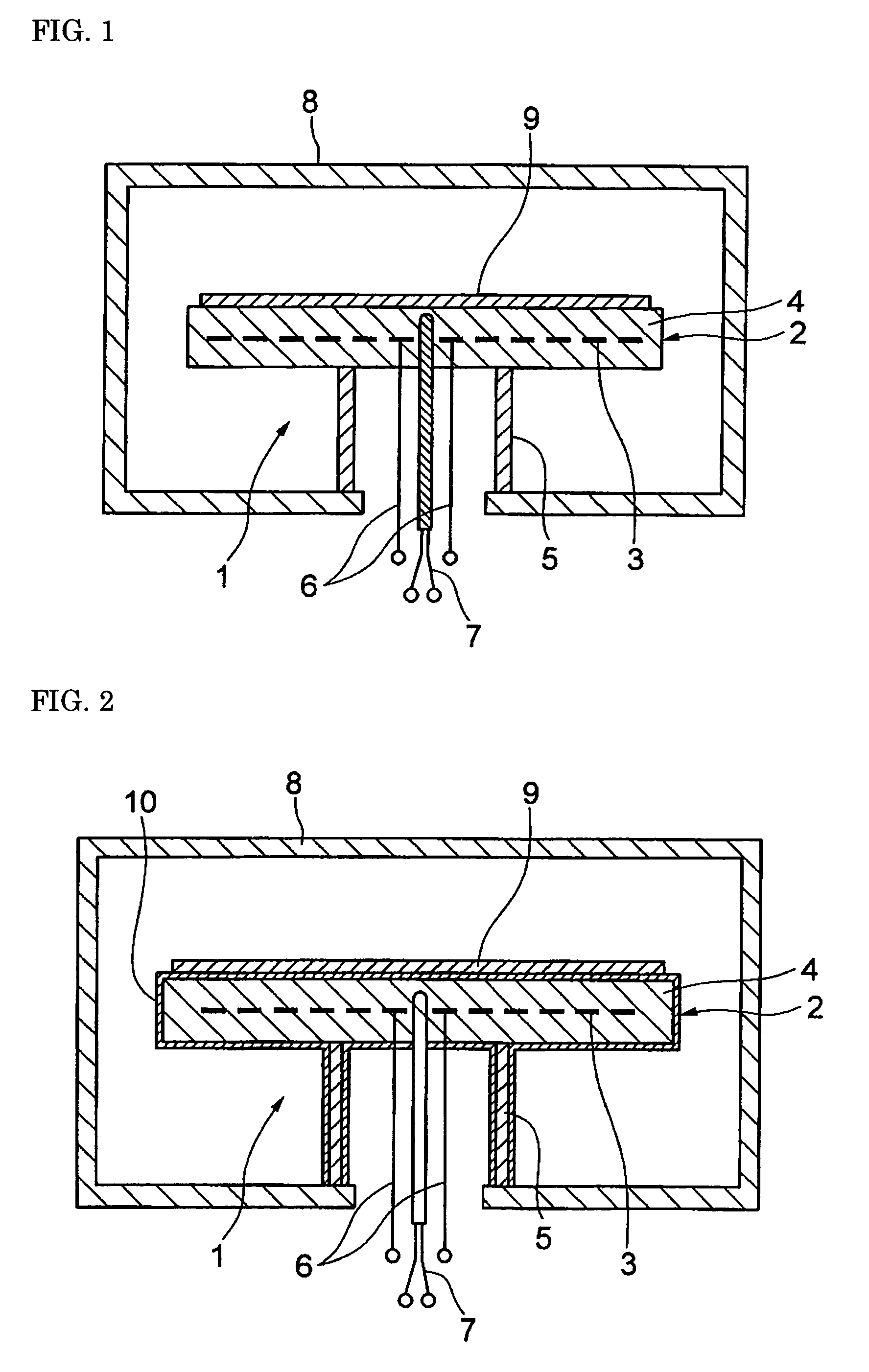
[0024]A to-be-placed-on-heat-subject heater member of the invention is described by referring to FIG. 2 showing a specific example thereof. This to-be-placed-on-heat-subject heater member 1 has a basic structure similar to the conventional one shown in FIG. 1, is structured by a heater substrate 2 including a ceramic base 4 with a heat-generating wiring section 3, and a tubular support body 5 made of ceramic or others, and is provided with a feed wiring configuration 6 electrically connected to the heat-generating wiring section 3, a thermocouple 7 for monitoring the heater temperature, and the like. The to-be-placed-on-heat-subject heater member of the invention is formed with a low-radiation-rate film 10 entirely over at least the heat-subject-placing surface of the heater substrate 2 on which at least a heat subject 9 is to be placed.

[0025]As shown in FIG. 2, the low-radiation-rate film 10 is preferably formed entirely over both the heater substrate 2 and the support body 5. More...


PUM

PropertyMeasurementUnit
thicknessaaaaaaaaaa
temperatureaaaaaaaaaa
thicknessaaaaaaaaaa

Abstract

A low-radiation-rate film, made of a material whose radiation rate is lower than that of a heater substrate, is formed at least entirely over the surface of a heat-subject-placing surface of a heater substrate. By applying patterning to the low-radiation-rate film, the exposure rate of the heater substrate is varied such that the radiation rate becomes smaller from the center part of the heat-subject-placing surface toward the outer peripheral part thereof, thereby enabling a uniform temperature across the surface. In addition, the power supply is reduced, thermal stress is eliminated, the wiring design flexibility is increased, and the reliability is increased by preventing short-circuit accidents.

Description

TECHNICAL FIELD[0001]The present invention relates to a to-be-placed-on-heat-subject heater member for heating a heat subject placed thereon, and a heat processor using the to-be-placed-on-heat-subject heater member.BACKGROUND ART[0002]Various types of heater members for heating a heat subject placed thereon have been conventionally proposed. For the purpose of heating semiconductor wafers, liquid crystal panel substrates, and others for processing, exemplified is a heater member mainly made of ceramic including aluminum nitride that provides high heat conductivity and high heat uniformity, or aluminum oxide that is low in price or others. As to such a heater member, various studies have been conducted with respect to its shape, structure, or the like, to achieve effective heating of heat subjects.[0003]As a specific example of such a conventional heater member mainly made of ceramic-based material, as shown in FIG. 1, there is a heater member for use in a heat processor such as a s...

Claims


Application Information

Patent Timeline
Patent Type & Authority Patents(United States)
IPC IPC(8): H05B3/68H05B3/00H05B3/20H01L21/00H01L21/205H01L21/3065H05B3/10H05B3/14H05B3/28H05B3/74
CPCH01L21/67103H05B3/143
Inventor NATSUHARA, MASUHIRONAKATA, HIROHIKOSHINMA, KENJI
Owner SUMITOMO ELECTRIC IND LTD
Why Eureka
Eureka Blog
Learn More