
Gas turbine nozzle segment and process therefor

a technology of gas turbine engine and nozzle segment, which is applied in the direction of liquid fuel engine, machine/engine, priming pump, etc., can solve the problems of irregular flattening grains of bond coat, degree of inhomogeneity and porosity, etc., and achieve the effect of improving durability and aerodynamic performan

Inactive Publication Date: 2008-03-11
GENERAL ELECTRIC CO
View PDF8 Cites 27 Cited by
  • Summary
  • Abstract
  • Description
  • Claims
  • Application Information

AI Technical Summary

Benefits of technology

"The present invention provides a gas turbine engine nozzle segment that is more durable and aerodynamic than previous versions. The process involves producing a nozzle segment with vanes between platforms, and depositing an environmental coating on its surface. The coating is made of a bond coat material and an oxidation-resistant coating. Cooling holes are drilled in the nozzle assembly, and an oxidation-resistant coating is applied on the smoothed surface. The nozzle segment can be installed in the gas turbine engine without a ceramic thermal barrier coating on its outermost surface. The use of the BC52 material as an environmental coating promotes smooth surface finish and superior oxidation and corrosion resistance compared to the BC22 material currently employed."

Problems solved by technology

Construction of a nozzle assembly with individual nozzle segments is often expedient due to the complexities of the cooling schemes typically employed.
As a result of the thermal spray deposition process, the molten powder particles deposit as “splats,” resulting in the bond coat having irregular flattened grains and a degree of inhomogeneity and porosity.

Method used


Image

  • Gas turbine nozzle segment and process therefor
  • Gas turbine nozzle segment and process therefor

Examples


Embodiment Construction

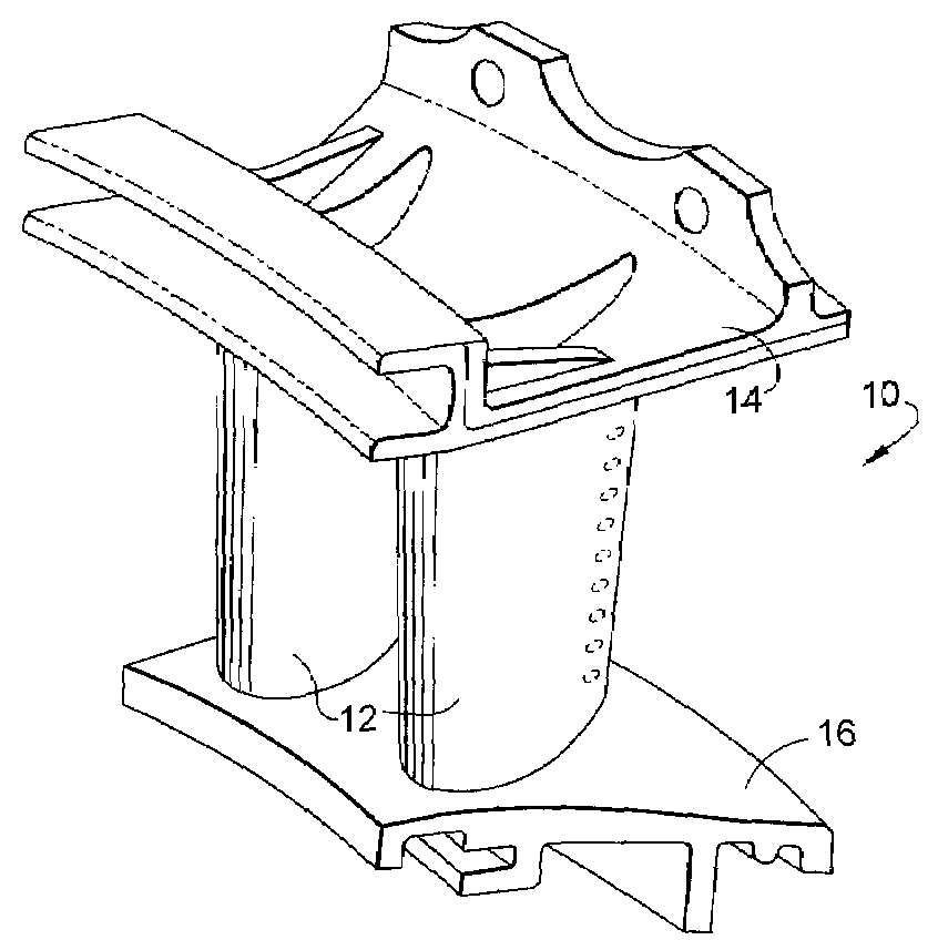
[0015]The present invention is generally applicable to components that operate within environments characterized by relatively high temperatures, and particularly to nozzle segments of the type represented in FIG. 1 and therefore subjected to severe oxidizing and corrosive operating environments. It should be noted that the drawings are drawn for purposes of clarity when viewed in combination with the following description, and therefore are not intended to be to scale.

[0016]An environmental coating system 20 in accordance with this invention is represented in FIG. 2 as comprising an environmental coating 22 overlying a wall region 18 of the nozzle segment 10 of FIG. 1, and a oxidation-resistant coating 24 overlying the environmental coating 22. According to a preferred aspect of the invention, the nozzle segment 10 is a casting of the gamma prime-strengthened nickel-base R125 superalloy, whose nominal composition is, by weight, about 10 percent cobalt, about 8.9 percent chromium, a...


PUM

PropertyMeasurementUnit
particle sizeaaaaaaaaaa
Raaaaaaaaaaa
surface roughnessaaaaaaaaaa

Abstract

A gas turbine engine nozzle segment and process for producing such a nozzle segment to exhibit improved durability and aerodynamic performance. The process produces a nozzle segment having at least one vane between and interconnecting a pair of platforms. The nozzle segment is cast from a gamma prime-strengthened nickel-base superalloy, on whose surface is thermal sprayed an environmental coating formed of a MCrAlX-type coating material. The surface of the environmental coating is then worked to cause the coating to have a surface finish of less than 2.0 micrometers Ra. Cooling holes are then drilled in the nozzle segment, after which an oxidation-resistant coating is applied on the smoothed surface of the nozzle segment so as to maintain an outermost surface on the nozzle segment having surface finish of less than 2.0 micrometers Ra.

Description

BACKGROUND OF THE INVENTION[0001]The present invention generally relates to components for the turbine sections of gas turbine engines. More particularly, this invention relates to a gas turbine engine nozzle segment and a process for producing such a nozzle segment to exhibit improved durability and aerodynamic performance.[0002]Components located in the high temperature sections of gas turbine engines are typically formed of superalloys. Though significant advances in high temperature capabilities have been achieved, superalloy components must often be air-cooled and / or protected with a coating to exhibit a suitable service life in certain sections of gas turbine engines. For example, components of the turbine, combustor, and augmentor sections that are susceptible to damage by oxidation and hot corrosion attack are typically protected by an environmental coating and optionally a thermal barrier coating (TBC), in which case the environmental coating is termed a bond coat that in c...

Claims


Application Information

Patent Timeline
Patent Type & Authority Patents(United States)
IPC IPC(8): F04D9/02
CPCF01D5/288F01D9/041F05D2220/31F05D2230/21F05D2230/31F05D2230/90F05D2260/95F05D2300/15F05D2300/611
Inventor FARMER, ANDREW DAVIDNAGARAJ, BANGALORE ASWATHALU, WENFENGLEE, CHING-PANGGUENTERT, JOSEPH MICHAEL
Owner GENERAL ELECTRIC CO
Learn More