
Surface plasmon resonance microscope using common-path phase-shift interferometry

a surface plasmon resonance and interferometer technology, applied in the field of surface plasmon resonance microscopes using commonpath phase-shift interferometer, can solve the problems of low resolution, inability to detect biomolecules of low molecular weight or low concentration, and developed system inability to meet the strict demands of real-time bia kinetic studies

Inactive Publication Date: 2008-03-04
PHALANX BIOTECH GROUP
View PDF9 Cites 19 Cited by
  • Summary
  • Abstract
  • Description
  • Claims
  • Application Information

AI Technical Summary

Benefits of technology

"The present invention provides an SPR microscope that uses common-path phase-shift interferometry to solve the phase drift problem resulting from external environmental variety, mechanical vibration, and light source fluctuation. The microscope is suitable for measuring the 2-dimensional variation of the phase perpendicular to the surface of an analyte. The microscope uses a coherent light source, a coupler, an electro-optic modulator, and an image camera to capture the interference pattern caused by the modulation of the phase difference between the S-wave and P-wave light. The phase difference between the fast and slow axes is obtained by changing the external voltage applied to the modulator, and a continuous distribution diagram of phase variation is then reconstructed from the several interference diagrams using a phase reconstruction method."

Problems solved by technology

Although this system has a high-throughput screening capability, its resolution is too low to permit the detection of biomolecules of low molecular weight or low concentration.
However, in common with other SPR phase imaging systems, the developed system was unable to satisfy the strict demands of real-time BIA kinetic studies because it lacked long-term stability.

Method used


Image

  • Surface plasmon resonance microscope using common-path phase-shift interferometry
  • Surface plasmon resonance microscope using common-path phase-shift interferometry
  • Surface plasmon resonance microscope using common-path phase-shift interferometry

Examples


Embodiment Construction

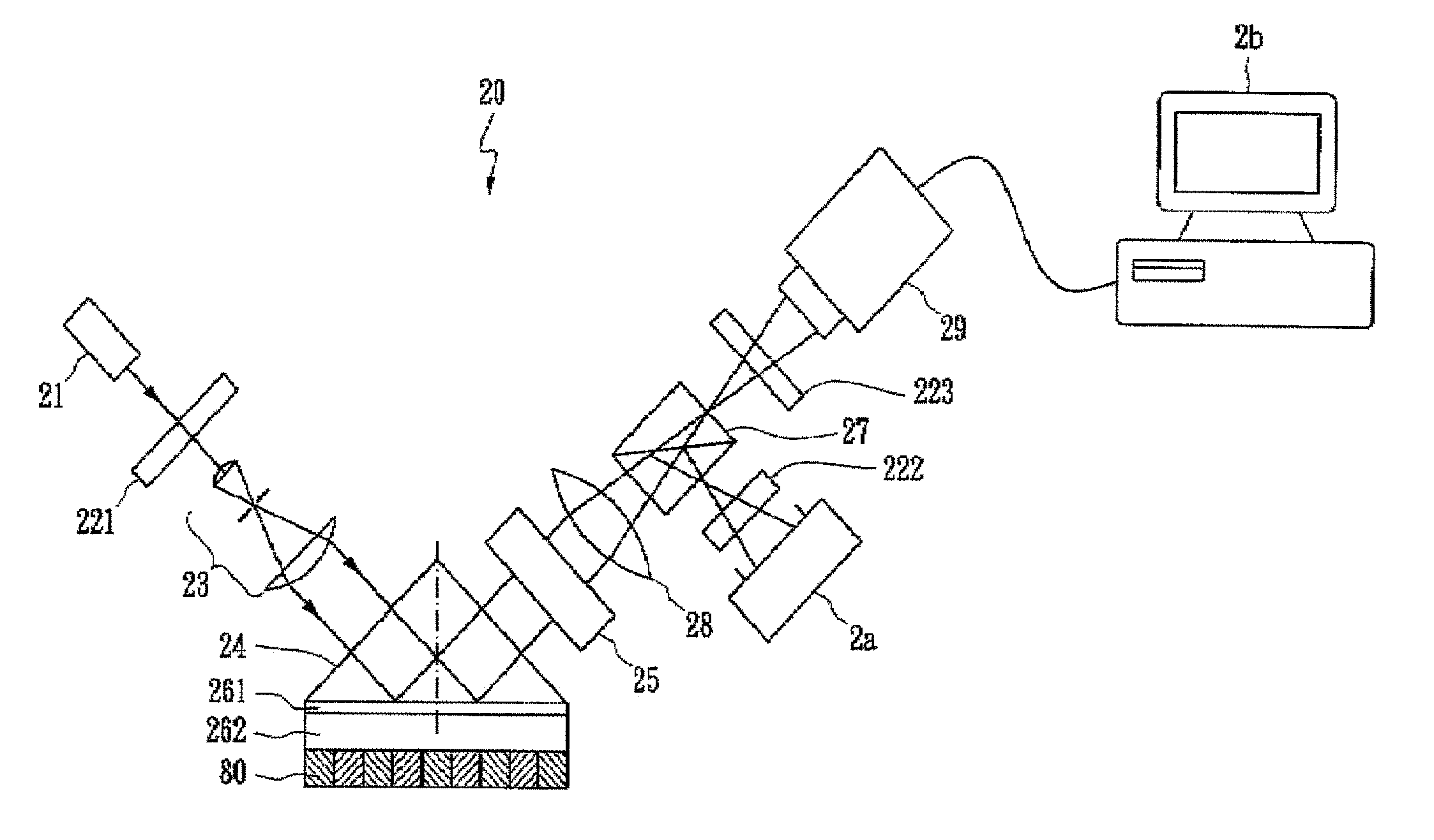
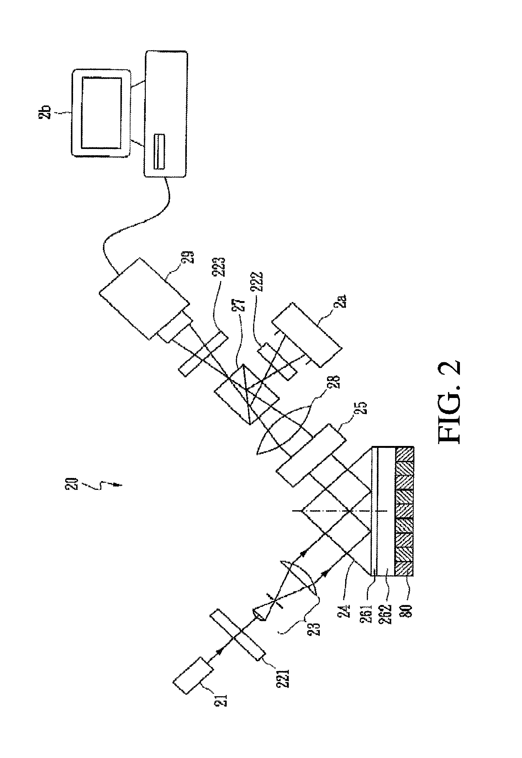
[0020]FIG. 2 is a schematic diagram of an SPR microscope using common-path phase-shift interferometry in accordance with the present invention. A coherent light source emits coherent light as an incident light—He—Ne laser with a 632.8 nm wavelength for example. The coherent light goes through a linear polarizer 221, and the optical components of the incident light, including P-wave light and S-wave light, are adjusted. Afterwards, the polarized light is changed into a plane beam by a beam expender 23. The plane beam enters a coupler 24 (as a prism in the embodiment) to excite the interface between a second metal film 262 and a sample layer 80 to generate SPW.

[0021]Because the characteristic of Au is quite stable, it is suitable to take Au with a dielectric constant of −10.8+1.47j at 632.8 nm as the second metal film 262. When Cr is taken as the material of the first metal film 261 for the sake of interface compensation, the adhesive force between the coupler 24 and the second metal ...


PUM


Abstract

The present invention integrates the surface plasmon resonance and common-path phase-shift interferometry techniques to develop a microscope for measuring the two-dimensional spatial phase variation caused by biomolecular interactions on a sensing chip without the need for additional labeling. The common-path phase-shift interferometry technique has the advantage of long-term stability, even when subjected to external disturbances. Hence, the developed microscope meets the requirements of the real-time kinetic studies involved in biomolecular interaction analysis. The surface plasmon resonance microscope of the present invention using common-path phase-shift interferometry demonstrates a detection limit of 2×10⁻⁷ refractive index change, a long-term phase stability of 2.5×10⁻⁴π rms over four hours, and a spatial phase resolution of 10−3 π with a lateral resolution of 100 μm.

Description

BACKGROUND OF THE INVENTION[0001]1. Field of the Invention[0002]The present invention relates to a surface plasmon resonance (SPR) microscope using common-path phase-shift interferometry and, more particularly, to a microscope which combines SPR and modified common-path phase-shifting interferometry to measure the spatial phase variation caused by bio-molecular interactions upon a sensing chip.[0003]2. Description of the Related Art[0004]As shown in FIG. 1, a surface plasmon wave (SPW) is a physical phenomenon existing in the interference between a metal layer (an Au layer or an Ag layer in the visible light region) and a nonconductive dielectric medium (air or water). Free electrons between the metal film 12 and dielectric medium 13 have collective resonance oscillations along the interface excited by that incident light 14 which is coupled to the metal film 12 through a coupler 11 (a prism). This free electron oscillation is called the SPW.[0005]A method of attenuated total reflec...

Claims


Application Information

Patent Timeline
Patent Type & Authority Patents(United States)
IPC IPC(8): G01B11/02
CPCG01N21/21G01N21/45G01N21/553G02B5/008G02B21/00B82Y20/00
Inventor SU, YUAN DENGCHEN, SHEAN JEN
Owner PHALANX BIOTECH GROUP
Learn More