
Pressure cleaner brush for washing surfaces

a technology for cleaning brushes and surfaces, applied in the direction of brushes, cleaning processes and apparatuses, applications, etc., can solve the problems of brush inconvenient use, inability to adjust the introduction and dissolving of detergent substances, and the known types of pressure cleaning brushes are not free from drawbacks. , to achieve the effect of avoiding unnecessary consumption

Inactive Publication Date: 2008-03-04
LEOPHORM
View PDF6 Cites 14 Cited by
  • Summary
  • Abstract
  • Description
  • Claims
  • Application Information

AI Technical Summary

Benefits of technology

"The present invention is a pressure cleaner brush for washing surfaces that allows the user to adjust the amount of detergent substances to be introduced in the water, based on different operating requirements. This avoids unnecessary consumption and allows the brush to be used during rinsing of soap-lathered surfaces. The brush does not require the use of specific and expensive detergents, making it more cost-effective. The brush is simple, easy to use, safe, and effective in operation. The brush includes a body with an impeller rotating inside it, which is turned by a jet of water from a nozzle associated with the body. The body also has an opening from which a rotating brush actuated by the impeller protrudes. The brush has at least one tank for containing detergent fluid, which is associated with the body. This invention solves the problem of excessive water consumption and provides a more efficient and cost-effective solution for cleaning surfaces."

Problems solved by technology

These known types of pressure cleaner brush, however, are not free from drawbacks, including the fact that they do not allow to adjust the introduction and dissolving of the detergent substances in the washing water.
In particular, it is noted that these brushes are not suitable to be used, for example, to rinse soap-lathered surfaces, since they do not provide for operation with only water flowing out, unless the tablets contained in them are used up completely.
Moreover, the tablets significantly affect the production and operating costs of conventional pressure cleaner brushes, and this is due to the specifications required for their insertion in the tube of said brushes.
Moreover, there is no possibility to use detergents other than tablets, such as for example commercial ones, which are far cheaper.
Another drawback affects known types of pressure cleaner brush that transmit motion from the impeller to the rotating brush by direct keying; while on the one hand this transmission allows the rotating brush to turn at high speeds, on the other hand it does not allow to give said brush enough torque for efficient operation.
More specifically, the rotating brush is not able to apply a force that is sufficient to overcome even the modest resistance offered by edges or uneven surfaces encountered by said brush during normal cleaning operations, and is disadvantageously subjected to alternating operation with frequent stops.
Transmission of motion by means of the conventional gear systems currently in use, instead, allows to reduce the rotation rate of the rotating brush, transmitting a higher torque to it; at the same time, however, said transmission is significantly bulky.

Method used


Image

  • Pressure cleaner brush for washing surfaces
  • Pressure cleaner brush for washing surfaces
  • Pressure cleaner brush for washing surfaces

Examples


Embodiment Construction

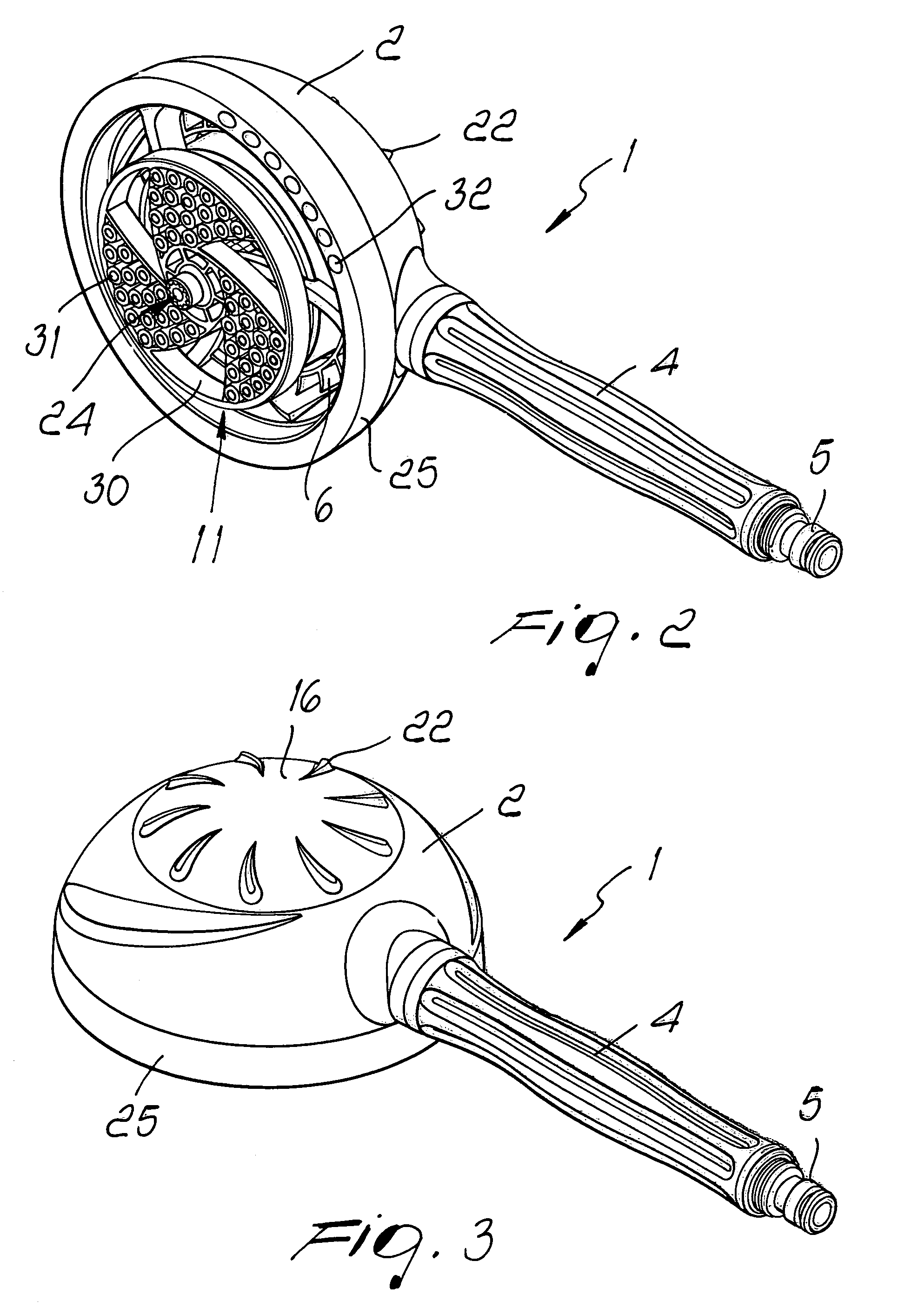
[0028]With reference to the figures, the reference numeral 1 designates a pressure cleaner brush for washing surfaces.

[0029]The brush 1 comprises a body 2, which is shaped like a half-shell and whose outer wall is crossed by a hole 3, which is connected to a rigid tube 4 that acts as a handle.

[0030]The free end of the rigid tube 4 is provided with a connecting element 5, which allows to connect the brush 1 to a water supply system, such as for example the ordinary water mains, a surge tank, a pump or the like.

[0031]A vaned or bladed impeller 6 is rotatably supported inside the body 2 and can be turned, during use, by means of a jet of water that arrives from a nozzle 7, which is tangent with respect to said impeller and is associated with the body 2.

[0032]Said nozzle is elongated and crosses the hole 3 from end to end, mutually connecting the rigid tube 4 and the body 2; it is in fact provided, at one end, with a head 8 that abuts against the internal surface of the body 2, and is a...


PUM


Abstract

A pressure cleaner brush for washing surfaces comprising a body inside which a bladed impeller is supported so that it can rotate, the impeller being turned by a jet of water that arrives from a nozzle that is associated with the body, the body being provided with at least one opening from which at least one rotating brush actuated by the impeller protrudes, and at least one tank for containing a detergent fluid, which is associated with the body.

Description

[0001]The present invention relates to a pressure cleaner brush for washing surfaces.BACKGROUND OF THE INVENTION[0002]As it is known, when washing surfaces such as for example windows, walls, floors, metal panels and the like, it is necessary to use brushes, cloths or the like together with the application of detergent substances mixed in water.[0003]Moreover, in performing these operations it is known to use pressure cleaner brushes, which comprise a half-shell inside which there is a bladed impeller, which is driven by a jet of water and transmits motion to a rotating brush that protrudes from said half-shell.[0004]Transmission of motion between the impeller and the rotating brush is commonly obtained by direct keying on said shaft or by interposing conventional gear systems, which generally allow to reduce the rotation rate between the driving wheel and the driven wheel.[0005]The jet of water that propels the vanes of the impeller conventionally arrives from a nozzle, which is ar...

Claims


Application Information

Patent Timeline
Patent Type & Authority Patents(United States)
IPC IPC(8): A46B13/04A46B13/06A46B13/02A47L1/08A47L11/03B08B1/04
CPCA46B13/06A47L11/03A47L11/4038A47L11/4069A47L11/4083B08B1/04B08B1/36B08B1/32
Inventor LEONARDI, LUCA
Owner LEOPHORM
Learn More