Method For The Regeneration Of A Particle Filter Installed In The Exhaust Gas Train Of A Vehicular Diesel Engine

Inactive Publication Date: 2009-08-06
MAN NUTZFAHRZEUGE OESTERR
View PDF14 Cites 11 Cited by
  • Summary
  • Abstract
  • Description
  • Claims
  • Application Information

AI Technical Summary

Benefits of technology

[0007]In contrast to conventional methods, the inventive method allows the soot particle-loaded particle filter to be regenerated only during the times that the exhaust brake is operating. This means that the inventive method can be applied only in conjunction with diesel engines which have an exhaust brake device, to which a butterfly valve installed in the exhaust gas train upstream of the particle filter and either upstream or downstream of the turbine of an exhaust gas turbocharger also belongs. The butterfly valve is usually in the pass-through position, but it is switched into its blocking position during a normal exhaust braking phase, as a result of which the gas backed up in the blocked-off area of the exhaust gas line cooperates with the pistons in the individual engine cylinders to increase the braking power. So that the engine does not stall out during the braking process, however, the butterfly valve is not completely closed, or a small bypass channel, located in the area of the butterfly valve and passing around it, is opened by a valve, so that a small amount of the gas can flow from the backed-up area into the following section of the exhaust gas line. Since the butterfly valve is closed when the driver releases the fuel throttle, almost no fuel is admitted for combustion. As a result, the exhaust gas is little more than the air ingested during the intake stroke.
[0009]Because every regeneration of the particle filter according to the inventive method leads to the consumption of a certain amount of fuel, it is advisable, before the initiation of a regeneration phase, to question, i.e., to determine, the necessity of a particle filter regeneration. This is done, for example, by detecting the pressure values representative of the degree to which the filter is loaded with soot particles, such as the exhaust gas backpressure in the exhaust gas train. It is also possible to specify in advance a value range for the degree of soot loading and either to set the regeneration process in motion immediately whenever the actual soot load lies within the specified value range, or, depending on the situation, to initiate it after a certain time delay. In this case, a certain nominal range will be predefined for the evaluation of the detected pressure values representative of the soot particle load. By comparing the transmitted actual pressure values with the pressure values of the nominal range, it is then possible, depending on the position of the actual pressure values within this range, to determine whether a regeneration is necessary at once or whether it can instead be started at a later time. In this way, it is possible to avoid the unnecessary consumption of fuel.

Problems solved by technology

Especially in the case of vehicles like route buses and delivery trucks, which are operating under non-steady-state conditions most of the time, this known method of initiating the regeneration of soot-loaded particle filters usually results in the consumption of comparatively large amounts of fuel, which, as a result of increasing fuel prices, is strongly reflected in vehicle operating costs.

Method used


Image

  • Method For The Regeneration Of A Particle Filter Installed In The Exhaust Gas Train Of A Vehicular Diesel Engine
  • Method For The Regeneration Of A Particle Filter Installed In The Exhaust Gas Train Of A Vehicular Diesel Engine
  • Method For The Regeneration Of A Particle Filter Installed In The Exhaust Gas Train Of A Vehicular Diesel Engine

Examples


Embodiment Construction

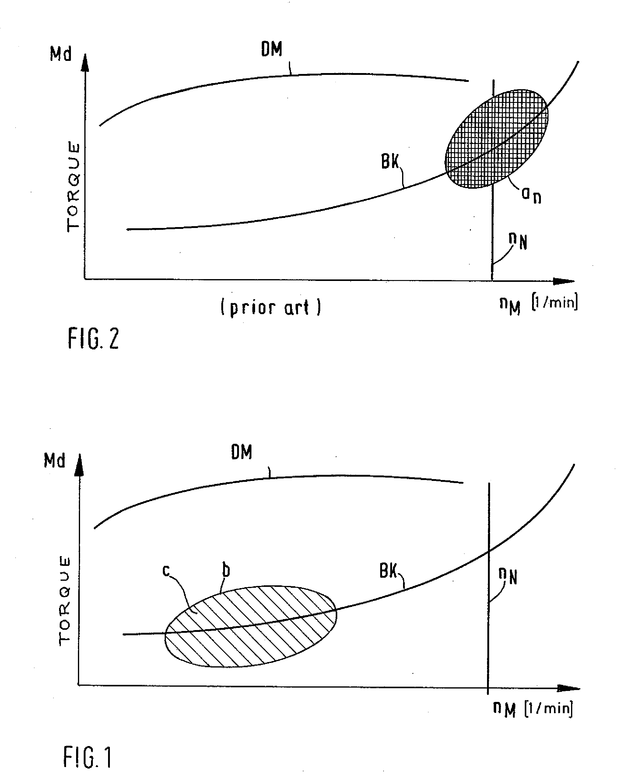
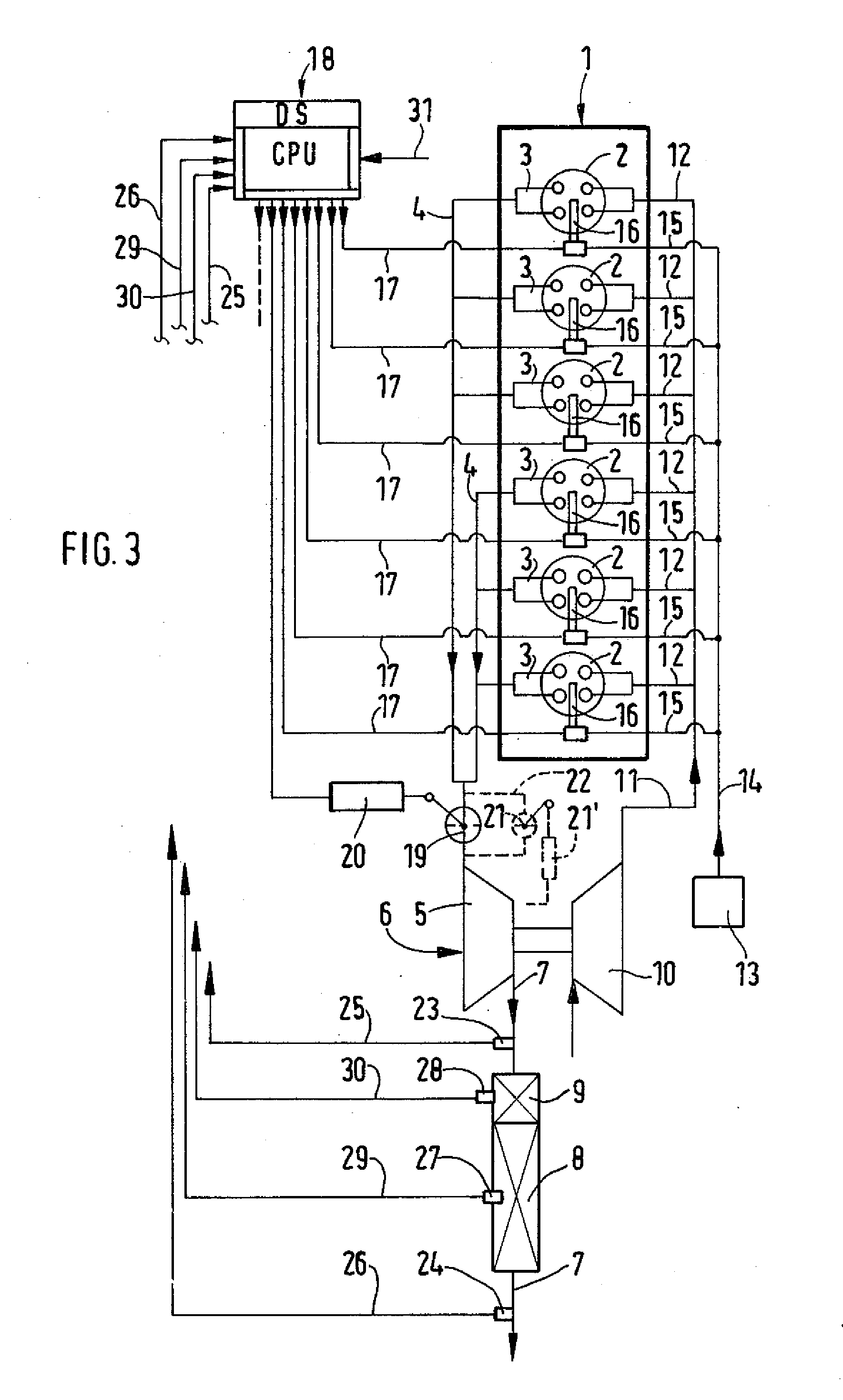
[0016]In the following, the inventive method is explained in greater detail on the basis of the diagram of FIG. 1 and a schematic diagram of a diesel engine according to FIG. 3.

[0017]FIG. 3 shows a schematic diagram of a diesel engine 1 installed in a vehicle such as a truck, bus, or other utility vehicle. Each of six cylinders 2 has two outlet valves, each of which communicates with an exhaust gas-collecting manifold 4 by way of an outlet channel 3. In the case shown here, the cylinders 2 are divided into two banks of three each, and each bank is connected to one manifold 4. Both manifolds 4 lead to the turbine 5 of an exhaust gas turbocharger 6 and are components of the exhaust gas train of the diesel engine 1, which, on the outlet side of the turbine 5, is connected to a section 7, in which a particle filter 8 is installed. In the example shown here, an oxidation catalyst 9 is installed upstream of the particle filter 8. This catalyst is responsible for producing a significant in...


PUM


Abstract

A method for regenerating a soot-laden particle filter in the exhaust gas train of a diesel engine in a vehicle, wherein the engine is equipped with a fuel injection system having an injection valve for each cylinder and an exhaust braking device including a butterfly valve in the exhaust gas train upstream of the particle filter. An exhaust braking phase is initiated by closing the butterfly valve, thereby causing hot exhaust gas to be compressed upstream of the butterfly valve. Regeneration of the particle filter is then initiated by injecting diesel fuel into the cylinders substantially after the respective pistons pass top dead center, and allowing the hot exhaust gas mixture containing unburned fuel and air to flow past the butterfly valve so that the mixture ignites the soot and then supports combustion of the soot, thereby regenerating the particle filter.

Description

BACKGROUND OF THE INVENTION[0001]1. Field of the Invention[0002]The invention relates to a method for the regeneration of a particle filter installed in the exhaust gas train of a vehicular diesel engine and partially loaded with separated soot particles, where the diesel engine is equipped with an exhaust brake device, to which a butterfly valve in the exhaust gas train upstream of the regeneration site belongs, and with a fuel injection system with an injection valve for each cylinder.[0003]2. Description of the Related Art[0004]In utility vehicles with diesel engines, particle filters are provided in the exhaust gas trains to satisfy the legally imposed exhaust gas regulations. Oxidation catalysts are installed upstream of the particle filters to increase the concentration of NOx in the exhaust gas, and in some cases SCR catalysts can be installed downstream. These particle filters are loaded to a greater or lesser extent with the soot separated from the exhaust gas. At sufficien...

Claims


Application Information

Patent Timeline
IPC IPC(8): F01N9/00F01N3/023
CPCF01N3/023F01N3/0235F02D9/06F02D41/025F02D41/029Y02T10/26F02D41/1448F02D41/40F02D41/405F02D2200/0802Y02T10/44F02D41/12Y02T10/12Y02T10/40
Inventor RICHTER, KLAUSRAAB, GOTTFRIED
Owner MAN NUTZFAHRZEUGE OESTERR
Why Eureka
Try Eureka