
Apparatus and method for measuring the wavefront of an optical system

a technology of optical system and wavefront, applied in the direction of measurement device, instrument, structural/machine measurement, etc., can solve the problems of limited detector resolution, interference pattern cannot be detected by the detector, severe limitation of the measurement range, etc., to increase the measurement range dynamics of the device, increase the measurement dynamics, and high the effect of measuring accuracy

Inactive Publication Date: 2008-02-26
CARL ZEISS SMT GMBH
View PDF6 Cites 47 Cited by
  • Summary
  • Abstract
  • Description
  • Claims
  • Application Information

AI Technical Summary

Benefits of technology

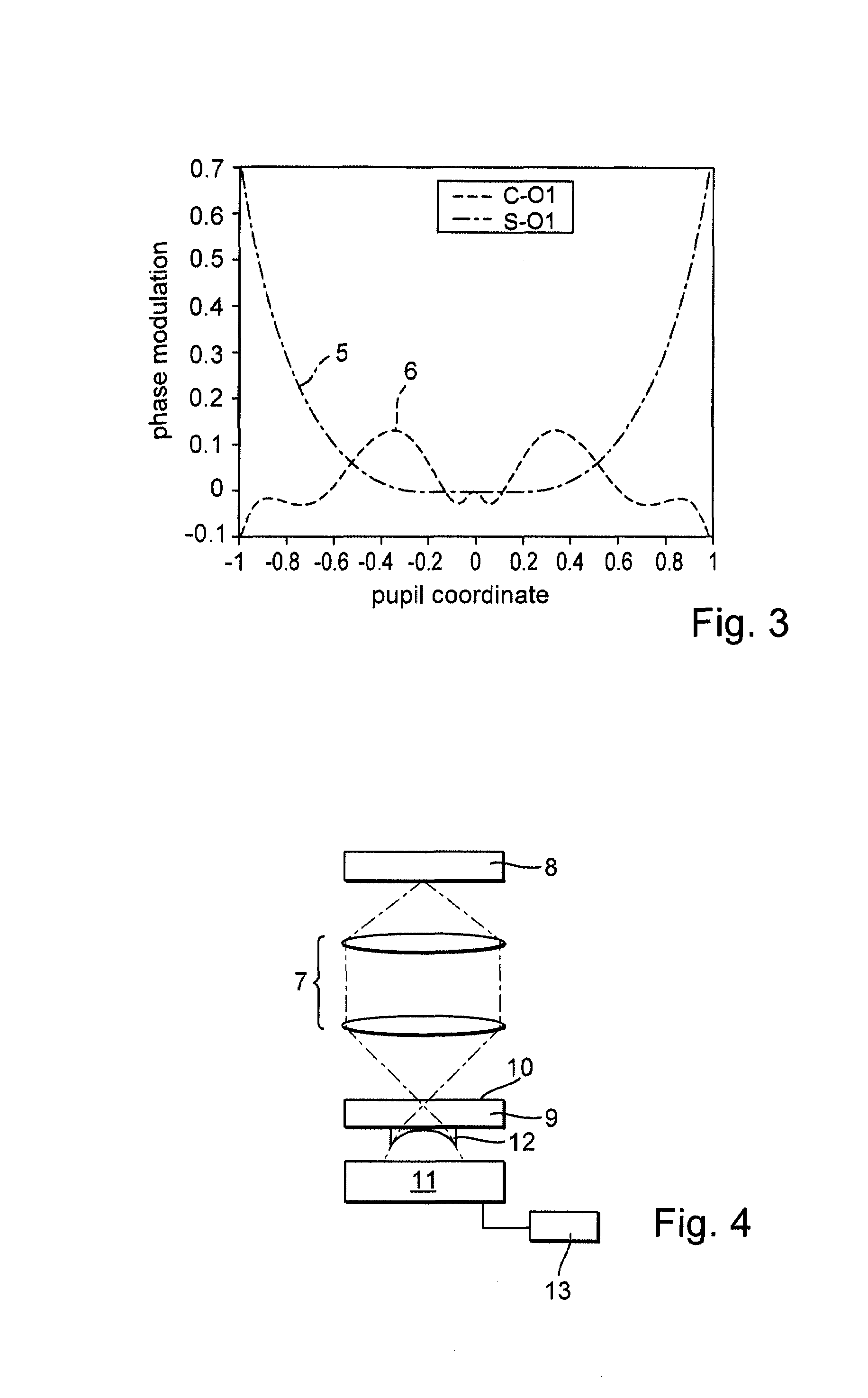
[0014]A lateral shearing interferometry technique is used in a refinement of this device. The dynamic range correction element is designed such that the second partial spatial derivatives of the wavefront to be determined are kept below a prescribable threshold value in the entire detection area, and this ensures the desired high dynamic range of the detection operation.
[0017]In a further aspect, for the purpose of solving the problem set, the invention includes a device for wavefront measurement of an optical system by means of a lateral shearing interferometry technique, having a mask structure element which can be positioned in the beam path upstream of the optical system, and a diffraction structure element which can be positioned in the beam path downstream of the optical system and has a periodic diffraction structure, and having a detector arrangement in the beam path downstream of the diffraction structure element for detecting an interference pattern of a wavefront, coming from the optical system, within a prescribable detection area. The device comprises a set of several diffraction structures, of different period lengths, and of corresponding mask structures of the mask structure element(s), in order to measure the optical system in various subareas of the detection area, or to measure the pupil with the aid of the diffraction structures of various period lengths and associated mask structures. This permits the selection of diffraction structure period lengths matched to the variation in the spatial characteristic of the interfering wavefront, and this corresponds to using various shearing distances for the shearing interferometry measurement in various subareas of the detection area. The measurement range dynamics of the device can be increased with the aid of this measure while maintaining a high measuring accuracy.
[0018]In a refinement of this device, at least for a first detection subarea a diffraction structure with a first period length is used, and for a second detection subarea with a wavefront phase modulation higher than in the case of the first detection subarea a diffraction structure with a greater period length than the first period length is used, it being possible thereby to increase the measurement dynamics in the desired way.
[0020]In a further aspect, the invention comprises a method for optical measurement of an optical system which comprises a detection of measuring radiation which comes from the optical system, and a determination and computational correction of a distortion error of the measuring radiation. The step of determining and computationally correcting the distortion error can be used to eliminate entirely or partially the influence of this error on the results of the measurement of the optical system. This comprises both applications in which a certain distortion error remains despite the use of a distortion correcting optics in a measuring device which carries out the method, and applications in which a relatively simple measuring optics is used and for this purpose the corresponding distortion error which is to be corrected computationally is accepted. The determination of the distortion error can be performed, for example, by calculating a distortion transformation by using a calculation of the optical beam path, for example by means of a corresponding ray-tracing algorithm, by an interferometric distortion error measurement by means of introducing reference patterns into a pupil, or a plane near the pupil, of a measuring optical imaging system, or into a plane conjugate therewith, or by a moiré measurement technique. A further advantageous distortion error determination includes a comparison of actual and desired positions of interference fringes of a generated and detected interference pattern when changing one or more external parameters. The change in the one or more external parameters particularly comprises a change in the position of a mask structure and / or a detector arrangement of the measuring device parallel to the main optical axis of the system, a change in the wavelength used and / or a change in the aberrations of the measured optical system, for example by adjusting existing xy-manipulators and / or z-manipulators for associated components of the measured system. The distortion is preferably corrected by applying the inverse distortion transformation after determining the distortion transformation describing the distortion error.

Problems solved by technology

This can lead to a severe limitation of the measurement range, specifically when measuring optical systems in the unadjusted state, or when measuring system parts or modules of optical systems having relatively large aberrations, that is to say the phase modulation of the wavefront to be detected exceeds a certain upper limit such that the interference pattern can no longer be detected by the detector with the desired resolution over the entire active detector surface if no counter measures are taken.
However, the detector resolution is limited by the minimum size of detector pixels, and the selection of a smaller shearing distance throughout the entire detection area, that is to say the entire detected cross section of the radiation measuring the optical system, leads in cases with very irregular variation in the wavefront to the fact that the signal-to-noise ratio becomes very small for a majority of the detector pixels, and it is therefore only a small portion of the detector pixels which make an effective contribution to the wavefront measurement with good reproducibility.
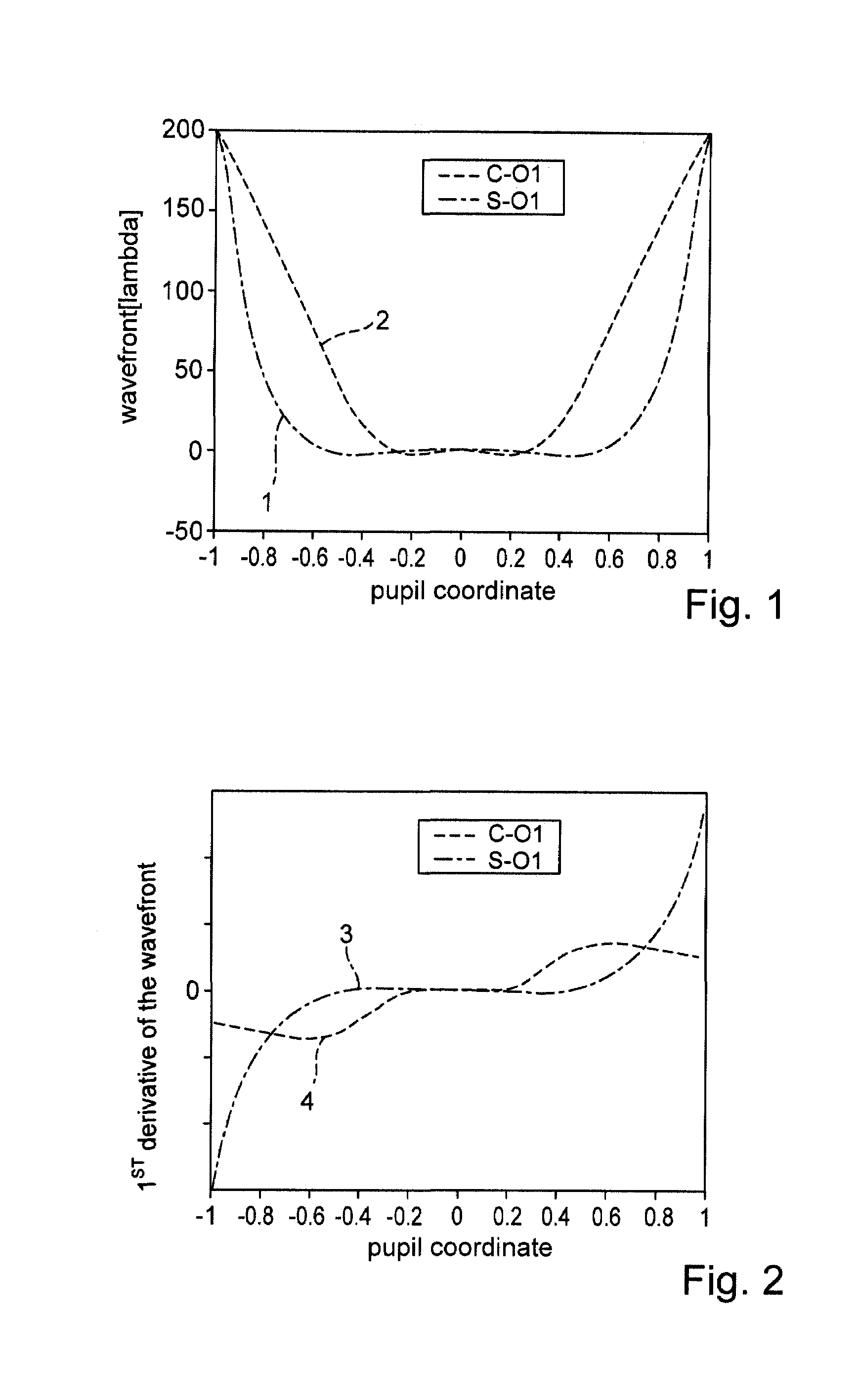
In the case of a measuring optical imaging system such as a microlithography projection lens, this means that the first spatial derivative of the wavefront in a pupil of the imaging system is substantially undistorted with the S-OI, whereas with the C-OI it is already in principle not imaged in a sinusoidally corrected fashion and therefore is imaged with a corresponding distortion error.
Depending on the detection system used, this can also be affected by a certain, slight distortion error.
Fizeau interferometers with C optics are also in use for wavefront measurement of optical systems, but are generally incapable of very compact design and are relatively susceptible to environmental influences.
Moreover, their coherent light source mostly results in so-called speckled effects.

Method used


Image

  • Apparatus and method for measuring the wavefront of an optical system
  • Apparatus and method for measuring the wavefront of an optical system
  • Apparatus and method for measuring the wavefront of an optical system

Examples


Embodiment Construction

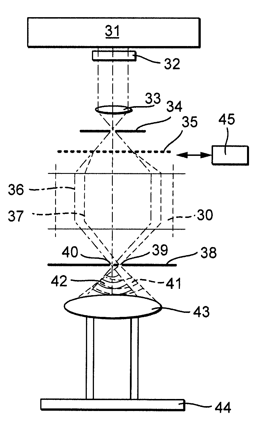
[0033]It is known that when measuring an optical imaging system by a lateral shearing interferometry technique that a modulation of intensity of the wavefront interference pattern formed is effected for a respective pixel (n, m) within a pupil of the imaging system by the lateral phase shifting, that is to say the lateral relative movement of object-side mask structure and image-side diffraction grating structure, and this modulation is proportional to a cosine function whose argument is equal to the sum of a spatially independent phase difference between mask and diffraction grating, and of a phase difference Δφ(xn, ym), dependent on the spatial coordinate (xn, ym) of the pupil point (n, m) considered, between two different, interfering diffraction orders, for example a 0th and a +1th diffraction order. Given a phase-shifting shearing movement in an x-direction, for example, this phase difference Δφ(xn, ym) is yielded by the relationship

Δφ(xn,ym)=φ(xn+s,ym)−φ(xn,ym),

φ denoting the ...


PUM


Abstract

A device and a method for wavefront measurement of an optical system (7), in particular by an interferometric measurement technique. A dynamic range correction element (12, 12a) is arranged in the beam path upstream of the detector arrangement (11) and is designed such that the variation in the spatially dependent characteristic of a phase of the wavefront forming the interference pattern is kept below a prescribed limit value throughout a detection area. In addition or as an alternative, a set of several diffraction structures of different period length can be used with a shearing interferometry technique and / or a set of several pairs of a reference pinhole and a signal passage opening with different hole spacings can be used with a point diffraction interferometry technique for different sub-areas of the detection area. A remaining distortion error can be taken into account by determining a corresponding distortion transformation and applying the inverse distortion transformation.

Description

BACKGROUND OF THE INVENTION[0001]1. Field of the Invention[0002]The invention relates to a device and a method for wavefront measurement of an optical system, in particular using an interferometric measurement technique.[0003]2. Description of the Related Art[0004]Such devices and methods are used, in particular, to determine the imaging quality of high accuracy imaging optics. An important application is the high accuracy measurement of the imaging behaviour of projection objectives in microlithography projection exposure machines. As an alternative to the use of a separate measuring site, it is possible in this case to provide to undertake the wavefront measurement of the objective in situ, that is to say in its installed state in the exposure machine. The measurement device is then integrated for this purpose in the exposure machine. The measurement of the objective is preferably performed at an operating wavelength, that is to say at that wavelength used by the exposure ma-chine...

Claims


Application Information

Patent Timeline
Patent Type & Authority Patents(United States)
IPC IPC(8): G01B9/02
CPCG01M11/0271G03F7/706
Inventor HAIDNER, HELMUTGOEPPERT, MARKUSSCHRIEVER, MARTINWEGMANN, ULRICH
Owner CARL ZEISS SMT GMBH
Learn More