
Spectrophotometer

a spectrophotometer and spectrophotometer technology, applied in the field of spectrophotometers, can solve the problems of less signal-to-noise ratio of measurement, waste of light of interest that is not collected and transmitted to the light detecting device, and difficulty in the illumination of the sample contained therein

Active Publication Date: 2008-02-26
AGILENT TECH AUSTRALIA M
View PDF18 Cites 2 Cited by
  • Summary
  • Abstract
  • Description
  • Claims
  • Application Information

AI Technical Summary

Benefits of technology

This configuration enhances the sensitivity and flexibility of the spectrophotometer, achieving superior signal-to-noise ratios and improved detection limits, especially when samples are partially filled, by ensuring uniform illumination and efficient light collection across the entire sample volume.

Problems solved by technology

Any light of interest that is not collected and transmitted to the light detecting device is wasted, and the signal-to-noise ratio of the measurement is less than it might otherwise be.
This long, narrow configuration of the sample container introduces difficulties in the illumination of the sample contained therein.
It also introduces difficulties in the collection of light of interest from the sample for detection and measurement.
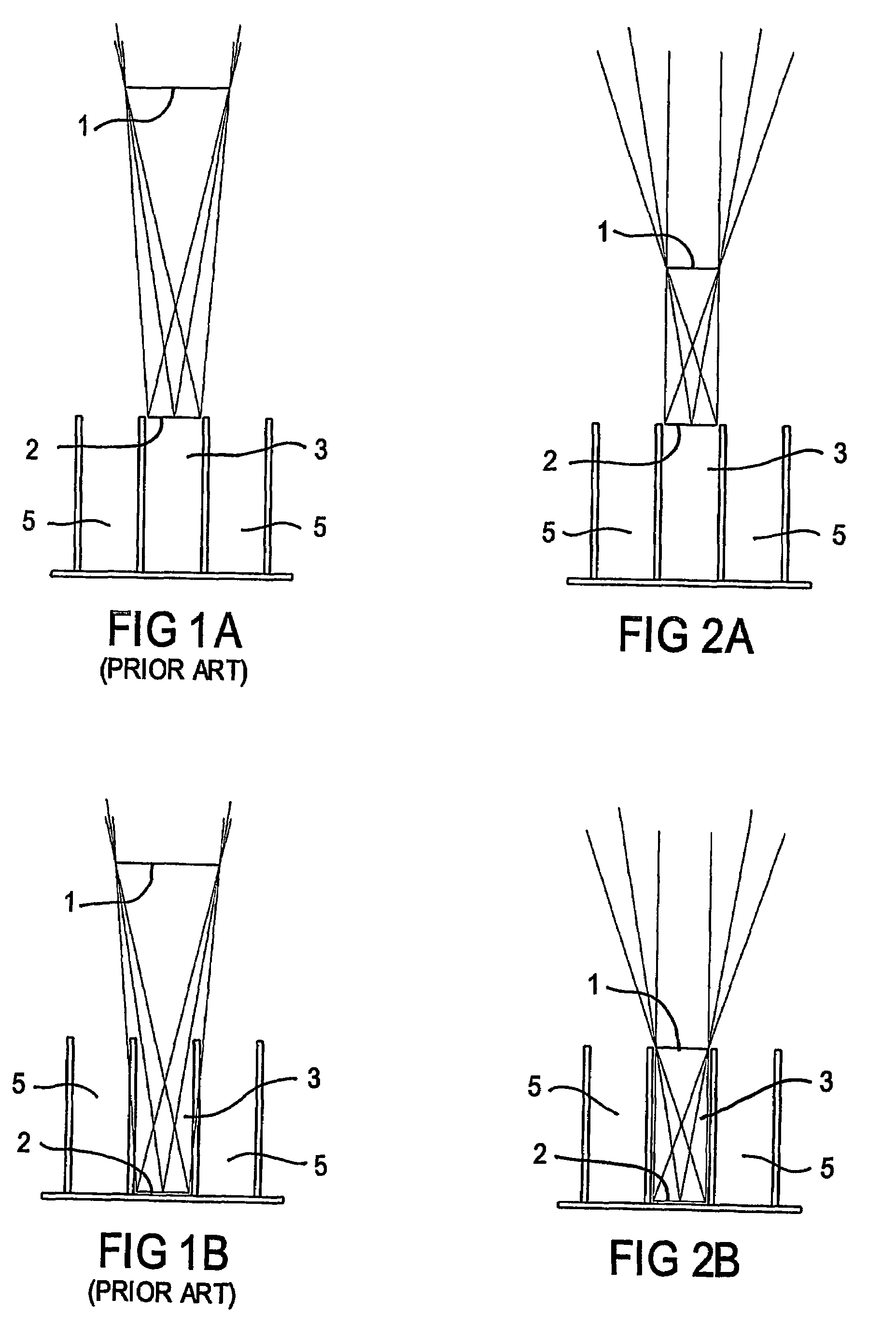
The limitation of this arrangement becomes evident when only a limited volume of sample is available and consequently the surface of the sample is considerably below the top of the well.
When absorbance measurements are being made any obstruction of light by the top edges of the well inevitably reduces the amount of light reaching the absorbance detector and thereby reduces the signal-to-noise ratio of the absorbance measurements.

Method used


Image

  • Spectrophotometer
  • Spectrophotometer
  • Spectrophotometer

Examples


Embodiment Construction

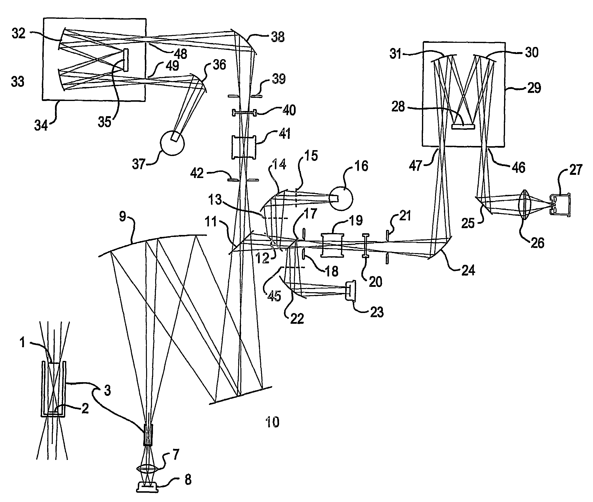
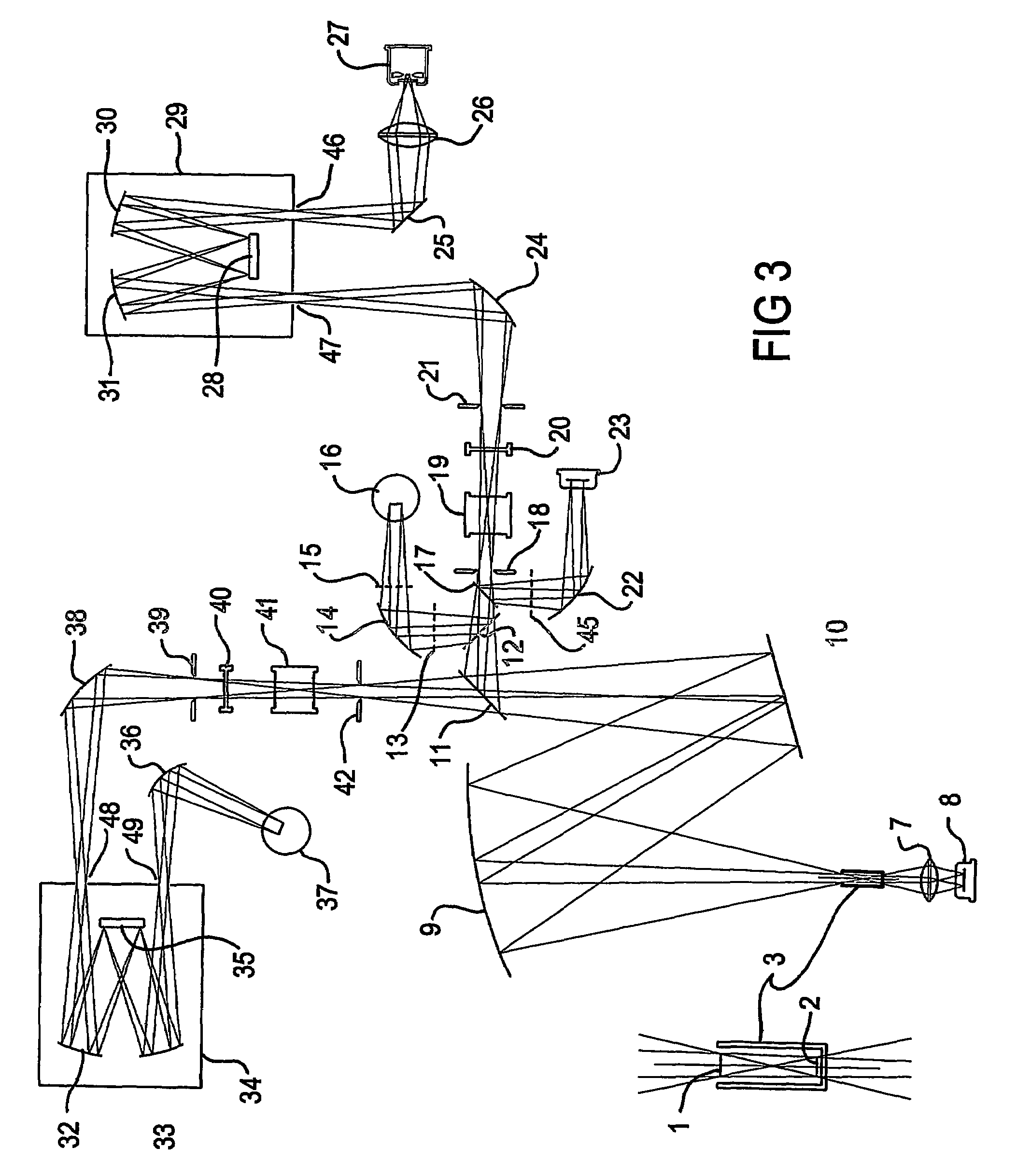
[0043]According to a preferred embodiment, a spectrophotometer includes a spectrophotometer including[0044]a light source,[0045]a sample position,[0046]and an optical system for directing a beam of substantially monochromatic light derived from the light source to a liquid sample when contained in a well when located at the sample position, the well having an internal shape,[0047]the optical system including,[0048](i) for deriving the beam of substantially monochromatic light, an entrance aperture followed by a second aperture associated with means for providing the substantially monochromatic light,[0049](ii) focussing means for providing conjugate images of the entrance and second apertures whereby there is established between the conjugate images a region of the beam of substantially monochromatic light that has a particular shape as determined by the shape and size of the conjugate images, and[0050](iii) imaging means for demagnifying and imaging the region of the beam of light ...


PUM

PropertyMeasurementUnit
volumeaaaaaaaaaa
sizeaaaaaaaaaa
internal sizeaaaaaaaaaa

Abstract

A spectrophotometer having an optical system for directing a beam of substantially monochromatic excitation light to a liquid sample contained in a well (3) of a well plate for interaction with the sample for absorption or emission measurements to analyse the sample. The optical system includes two apertures (46, 28) for establishing a Kohler illumination region outside the well, that is an excitation beam region between conjugate images (18, 21) of the two apertures. This excitation beam region is then demagnified and imaged (10, 9) into the well (3). The invention provides for the shape of the Kohler illumination region to correspond to the shape of the well space so that all of the liquid sample is uniformly illuminated without the well obstructing any portion of the illuminating excitation beam of light. Advantages of the invention are that the Kohler illumination region of the excitation beam is convenient for insertion of filters (20), apertures and polarisers (19) into the excitation optical system and permits use of small and thus cheaper filters and polarisers. Also the invention provides for accurate absorption or emission measurements from a liquid sample in a well notwithstanding that the sample may only partially fill the well.

Description

TECHNICAL FIELD[0001]The present invention relates to a spectrophotometer for the analysis and characterisation of samples by measurement of their absorption or fluorescence spectra, particularly when the analytical samples are liquid samples presented to the spectrophotometer in a well plate.BACKGROUND OF THE INVENTION[0002]The following discussion of the background to the invention is included to explain the context of the invention. This is not to be taken as an admission that any of the material referred to was published, known or part of the common general knowledge in Australia as at the priority date of any of the claims.[0003]Analytical samples can be characterised and analysed by spectrophotometric measurements of the absorption of light by a sample. Analytical samples can also be characterised and analysed by spectrophotometric measurements of the fluorescence of a sample.[0004]To perform a spectrophotometric measurement of the absorption of light by a sample a source of s...

Claims


Application Information

Patent Timeline
Patent Type & Authority Patents(United States)
IPC IPC(8): G01J3/42G01J3/32G01J3/443G01J3/02G01J3/10G01J3/44G01N21/25
CPCG01J3/02G01J3/0208G01J3/0224G01J3/10G01J3/42G01J3/44G01N21/253
Inventor SUN, YIN SHENGMASTERS, MARTIN KEITH
Owner AGILENT TECH AUSTRALIA M
Learn More