
System and method for breaking a feedback loop using a voltage controlled voltage source terminated subnetwork model

a subnetwork model and voltage control technology, applied in the field of electronic circuits, can solve the problems of multiple measurements, inability to replace and calculate the feedback function, and high cost, and achieve the effect of avoiding the possibility of failure, and avoiding failur

Active Publication Date: 2008-02-19
NAT SEMICON CORP
View PDF8 Cites 7 Cited by
  • Summary
  • Abstract
  • Description
  • Claims
  • Application Information

AI Technical Summary

Benefits of technology

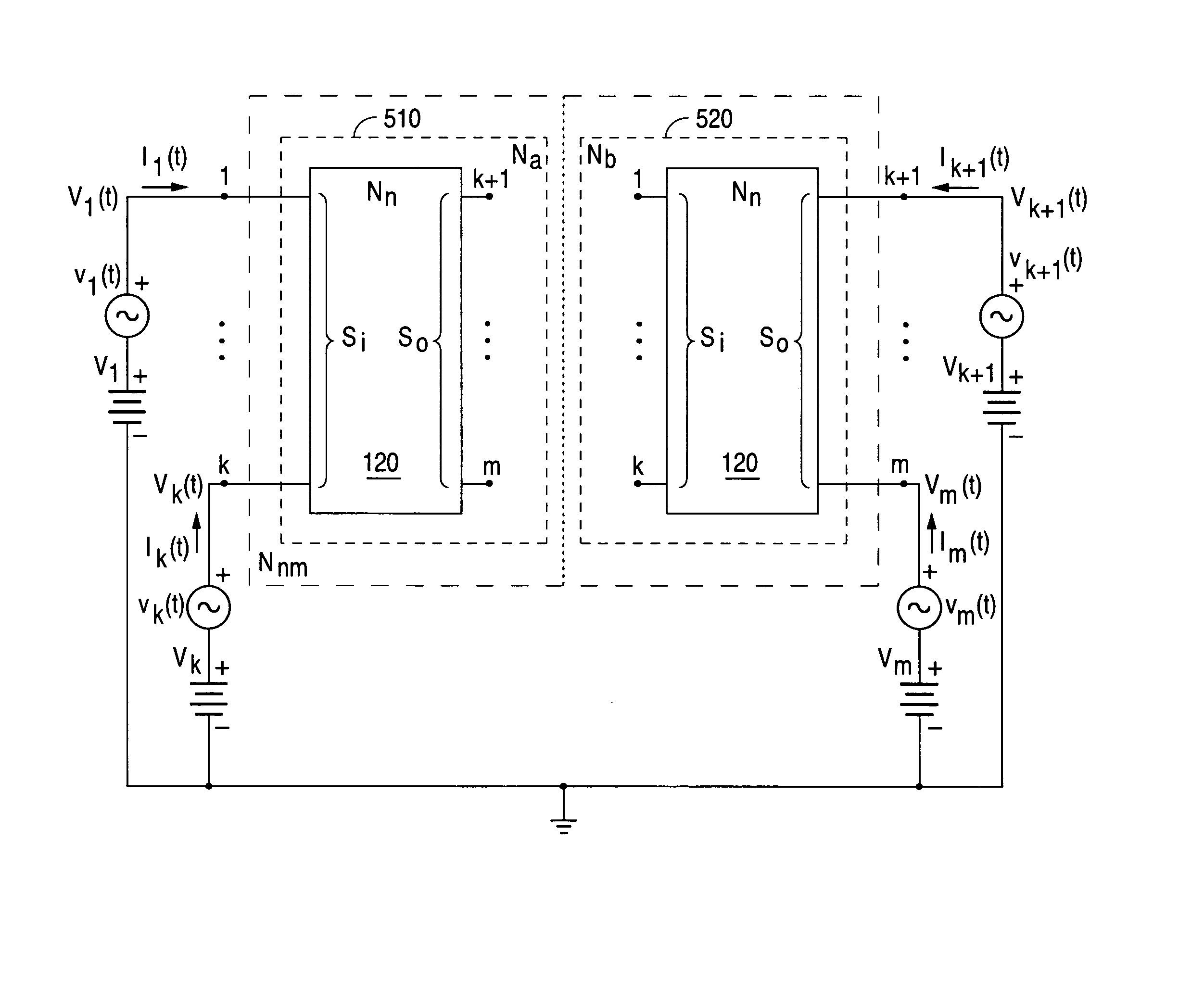
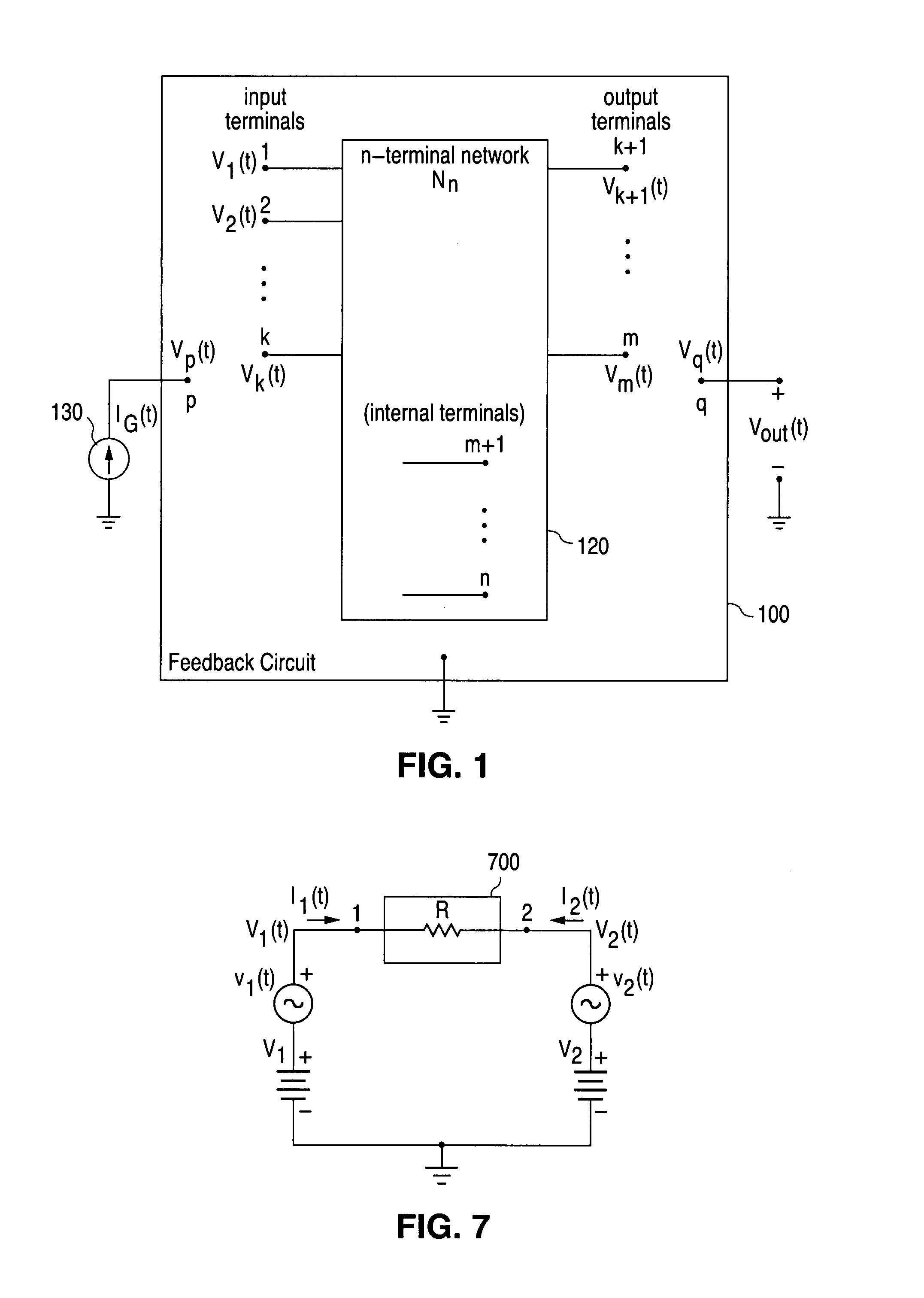
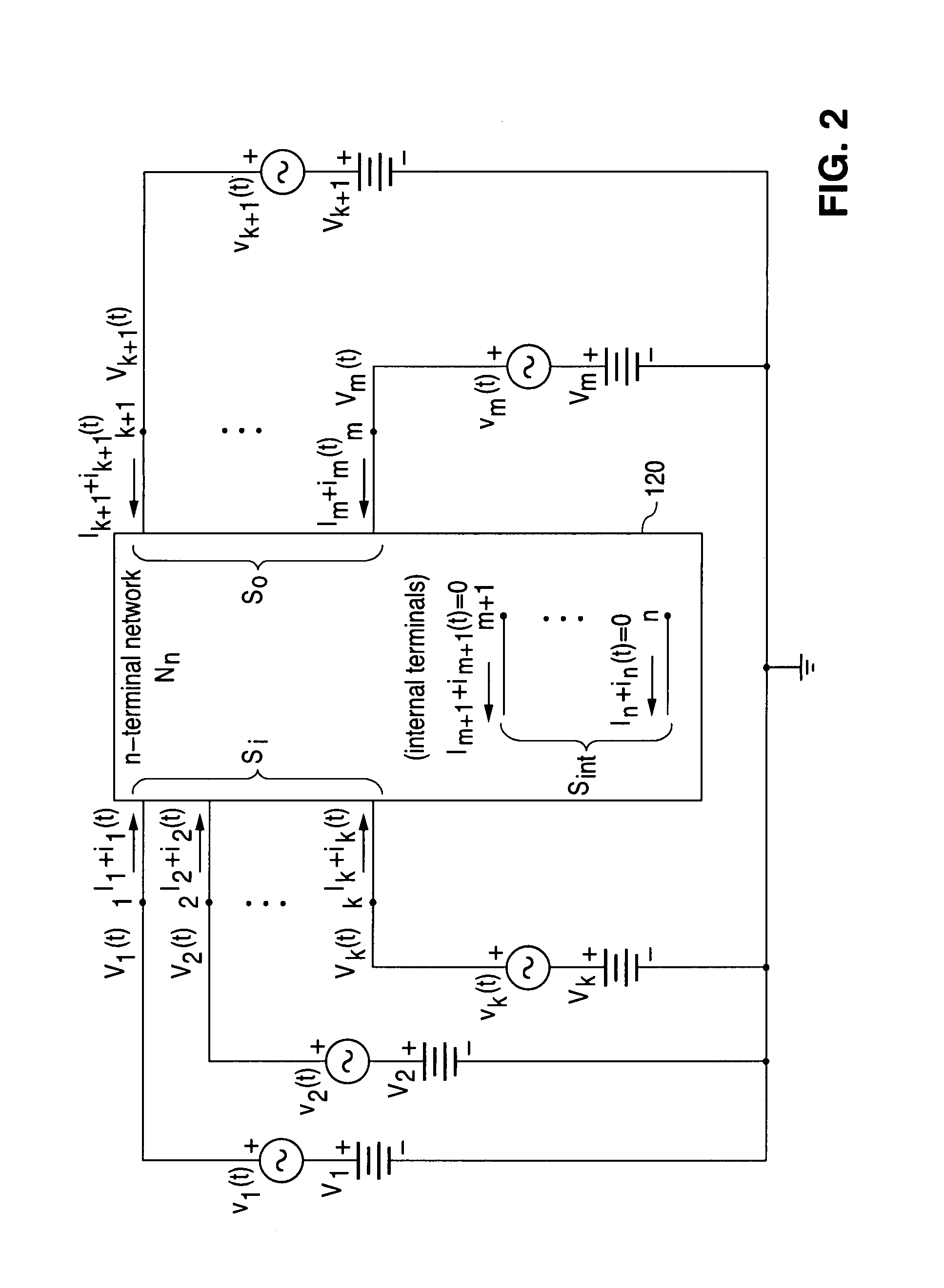
"The present invention provides an efficient system and method for breaking a feedback loop in a feedback circuit, where the components of the feedback loop are not required to be represented as two-port components. The invention uses a model that contains two physically disconnected subnetworks that have terminals that are connected to ground with voltage controlled, voltage sources. The invention allows for the control of lateral signal transfer and maintains a closed-loop direct current (dc) condition while simultaneously enabling an open-loop alternating current (ac) condition. The invention also provides a system and method for generating a voltage controlled voltage source terminated subnetwork model of at least one circuit component in a feedback circuit and simulating it in a software based circuit simulator. The technical effects of the invention include improved efficiency, accuracy, and flexibility in analyzing and evaluating circuit behavior under open-loop conditions."

Problems solved by technology

One problem with this method occurs in the application of the method to circuits that use complex transistor models.
The dependent sources in these models are often deeply embedded in such a way that they are not easily accessible for replacement and calculation of the feedback function.
A major problem with this method is the necessity of performing multiple measurements required to generate the two transfer functions.
Another problem that is likely to be encountered with the prior art methods is associated with their application in SPICE simulations.
Consequently, the small-signal alternating current (ac) models of transistors and other non-linear devices will not be accurate because these models must be determined at closed-loop direct current (dc) values.
These prior art methods cannot be used if these operations cannot be performed (or are not performed).

Method used


Image

  • System and method for breaking a feedback loop using a voltage controlled voltage source terminated subnetwork model
  • System and method for breaking a feedback loop using a voltage controlled voltage source terminated subnetwork model
  • System and method for breaking a feedback loop using a voltage controlled voltage source terminated subnetwork model

Examples


Embodiment Construction

[0049]FIGS. 1 through 22, discussed below, and the various embodiments used to describe the principles of the present invention in this patent document are by way of illustration only and should not be construed in any way to limit the scope of the invention. Those skilled in the art will understand that the principles of the present invention may be implemented in any type of suitably arranged feedback circuit.

[0050]A typical feedback loop generally contains a diverse variety of electronic components. These components consist of the usual passive elements such as resistors, capacitors, and inductors, and active devices such as bipolar junction transistors (BJT), field-effect transistors (JFET and MOSFET), and operational amplifiers (op-amps). Complex multi-terminal subcircuits made from combinations of these components are also present in feedback loops. A generalized voltage-controlled, voltage source (VCVS) terminated subnetwork model that is suitable for representing a general a...


PUM


Abstract

A system and method is disclosed for breaking a feedback loop by replacing at least one component in the feedback loop with a model containing two physically disconnected subnetworks that have terminals that are connected to ground with voltage controlled, voltage sources (VCVSs). Dependent source parameters of the VCVSs control lateral signal transfer though the model allowing the feedback loop to be opened or closed. The model maybe used in a software simulation in which a replicate circuit is used to set and maintain a closed-loop bias on the open-loop circuit. Small-signal analysis of the equivalent open-loop circuit allows extraction of transfer functions that yield a return ratio RR(s) corresponding to the modeled component.

Description

TECHNICAL FIELD OF THE INVENTION[0001]The present invention is generally directed to electronic circuits of the type that comprise a feedback loop and, in particular, to a system and method for breaking a feedback loop using a voltage controlled voltage source (VCVS) terminated subnetwork model.BACKGROUND OF THE INVENTION[0002]In performing computer aided analysis and simulation of feedback circuits, it is often desirable to break the feedback loop to study and evaluate circuit behavior under open-loop conditions. One of the most important performance specifications determined from open-loop configurations is stability. When the feedback loop is properly broken then stability is easily determined from frequency response plots of the gain around the loop (known as loop-gain).[0003]Quantitative measures of stability as well as approximate degrees of stability can be determined from performance parameters taken from the log magnitude and phase plots (Bode plots) of loop-gain. Gain marg...

Claims


Application Information

Patent Timeline
Patent Type & Authority Patents(United States)
IPC IPC(8): G06F17/50
CPCG06F17/5036G06F17/5063G06F30/36G06F30/367
Inventor RUSSELL, JR., HOWARD T.
Owner NAT SEMICON CORP
Learn More