Phased array ultrasonic NDT system for fastener inspections

a phased array and ultrasonic technology, applied in the direction of instruments, specific gravity measurement, magnetic property measurement, etc., can solve the problems of mechanical complexity, obsolescence and no longer maintainable, and serious structural failur

Inactive Publication Date: 2008-02-12
R D TECH +1
View PDF10 Cites 13 Cited by
  • Summary
  • Abstract
  • Description
  • Claims
  • Application Information

AI Technical Summary

Benefits of technology

[0012]This centering rod is positioned centrally with respect to the conic array of elements, located inside a sleeve formed in a variant on the standard “boot” used in ultrasonic devices. This boot is fitted to the forward end of the conic probe with its flanges firmly anchored to the probe housing. As the boot is donut-like in shape, it is able to contain water to provide an acoustic transmission column for the ultrasonic beams, while permitting the centering rod freedom to move within the central sleeve.
[0013]According to a further feature of the invention, an operator-assisting positioning system is preferably provided in the form of four illuminated sources (e.g., light emitting diodes) arranged in the pattern of a cross. When all four sources are lit, the operator is informed that centering within a preset tolerance limit has been achieved. Otherwise, the illumination of a single source provides a signal that the probe assembly should be displaced in the direction of the illumination. When two contiguous sources are illuminated, a signal is provided that the probe assembly should be displaced in an oblique direction, passing between the two illuminated sources. In this manner, an operator is given a ready indication as to positioning the probe assembly substantially centrally over the fastener opening to be tested. Once the probe is within 0.030 of an inch of being centered, no further centering is needed. Using phased array ultrasonic examination, the exact position of the probe with respect to the fastener can be determined and, using its steering ability, the system can compensate for the residual positioning error while performing the scan.

Problems solved by technology

Aircraft fastener holes are prone to developing cracks that can propagate and result in serious structural failure.
The current system has been in service for many years, but is now obsolescent and no longer maintainable.
Its drawbacks include a mechanically-complex scanner that requires the physical rotation of two conventional single-element ultrasonic probes (sequentially—one in each direction around the entire circumference of the hole) that requires a long inspection time of up to several minutes per fastener hole.
Further, it is necessary to center the scanner very precisely over the hole, which contributes to the length of the inspection, particularly because the scanner is of such weight that it must be supported by a floor stand when conducting under-wing inspections.

Method used


Image

  • Phased array ultrasonic NDT system for fastener inspections
  • Phased array ultrasonic NDT system for fastener inspections
  • Phased array ultrasonic NDT system for fastener inspections

Examples


Embodiment Construction

Detection Requirement

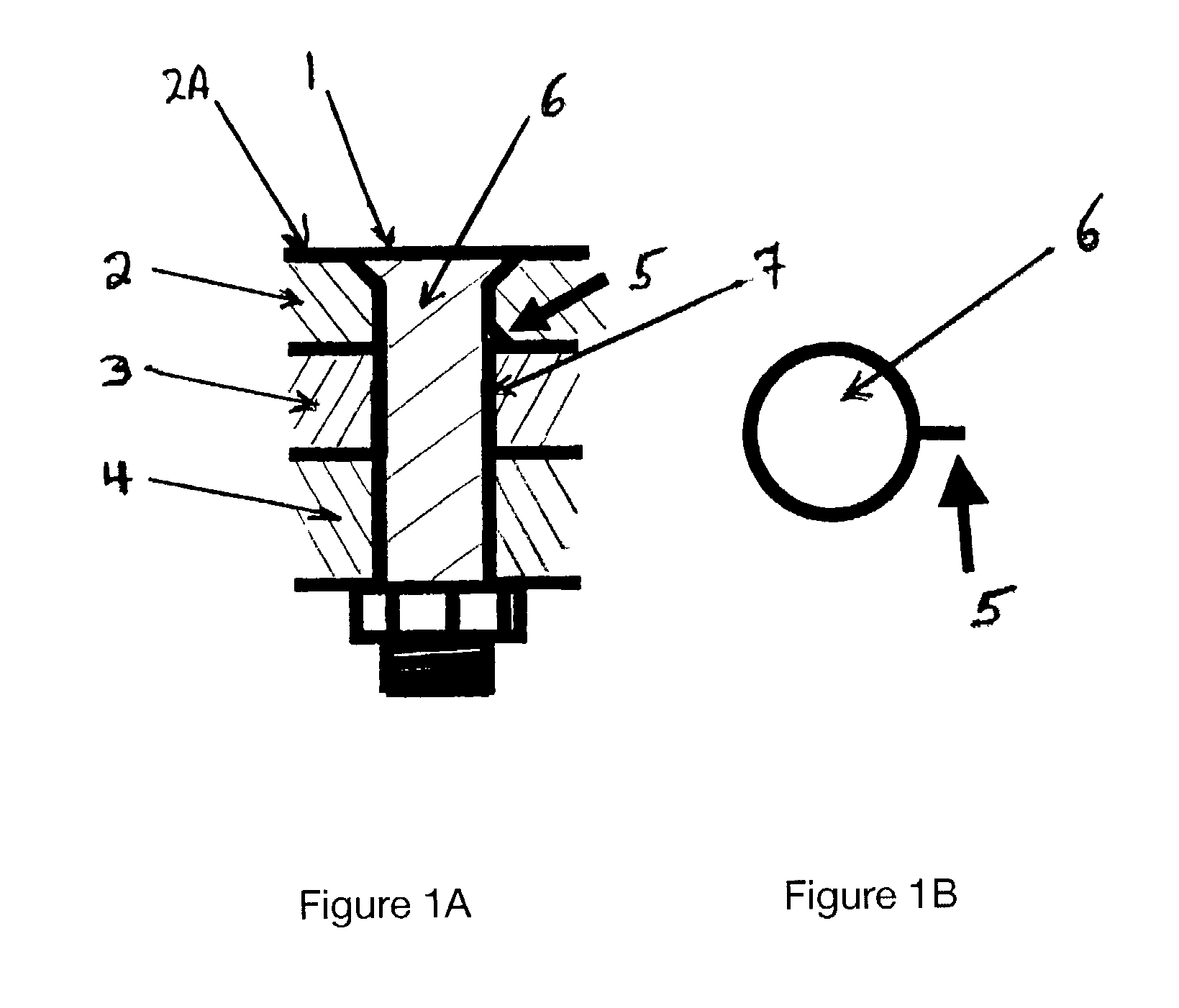
[0052]In the preferred embodiment of the invention, the object is to detect defects anywhere around the fastener hole wherein the defects are at least 0.030 of an inch in length. Typical fastener diameters range from 3 / 16 to 5 / 16 of an inch and skin thicknesses from 0.117 to 0.310 of an inch. FIG. 1A illustrates fastener 1 holding together layers 2, 3 and 4 of, typically, aluminum with faying surface crack 5 in first skin layer 2. FIG. 1B further illustrates crack 5 in a top view.

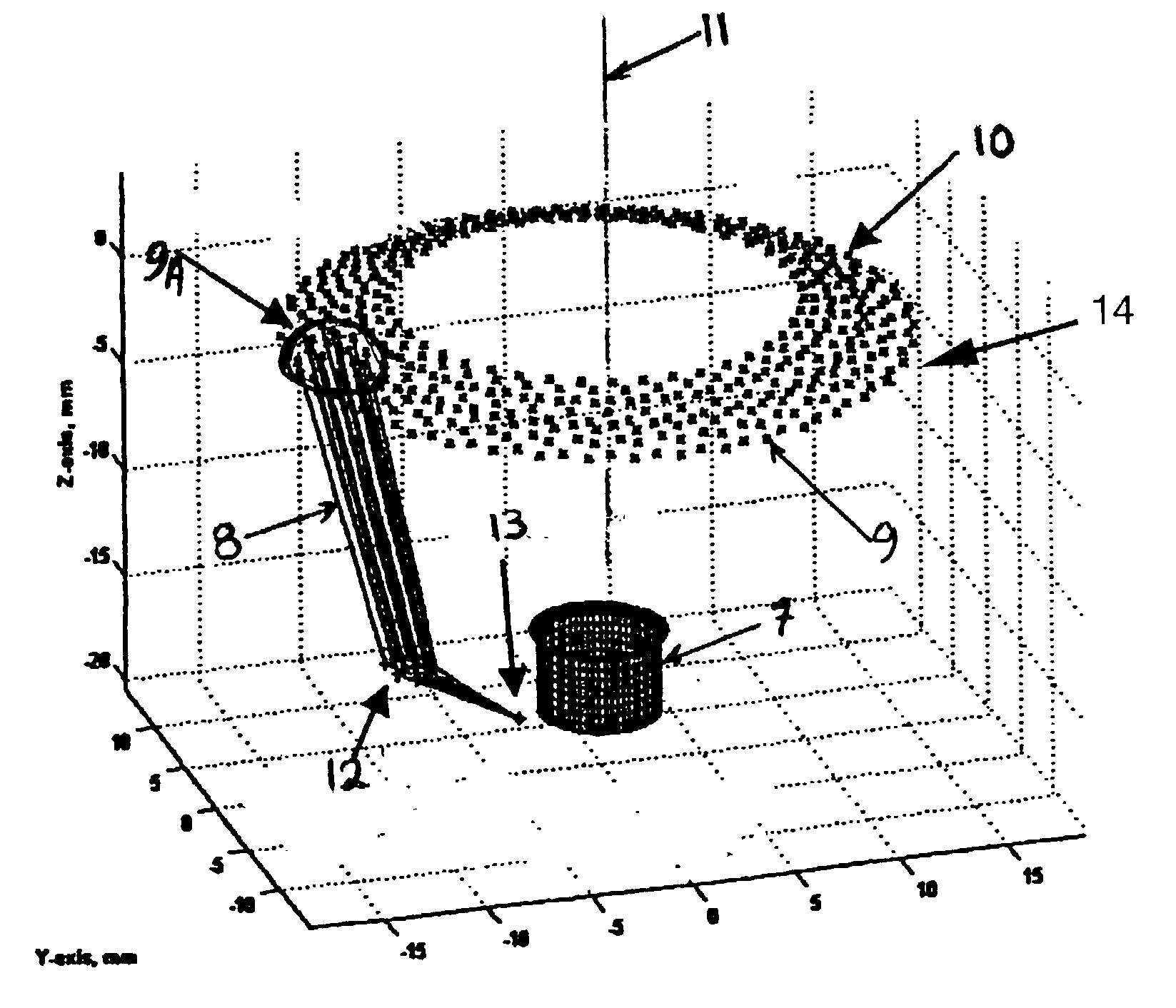
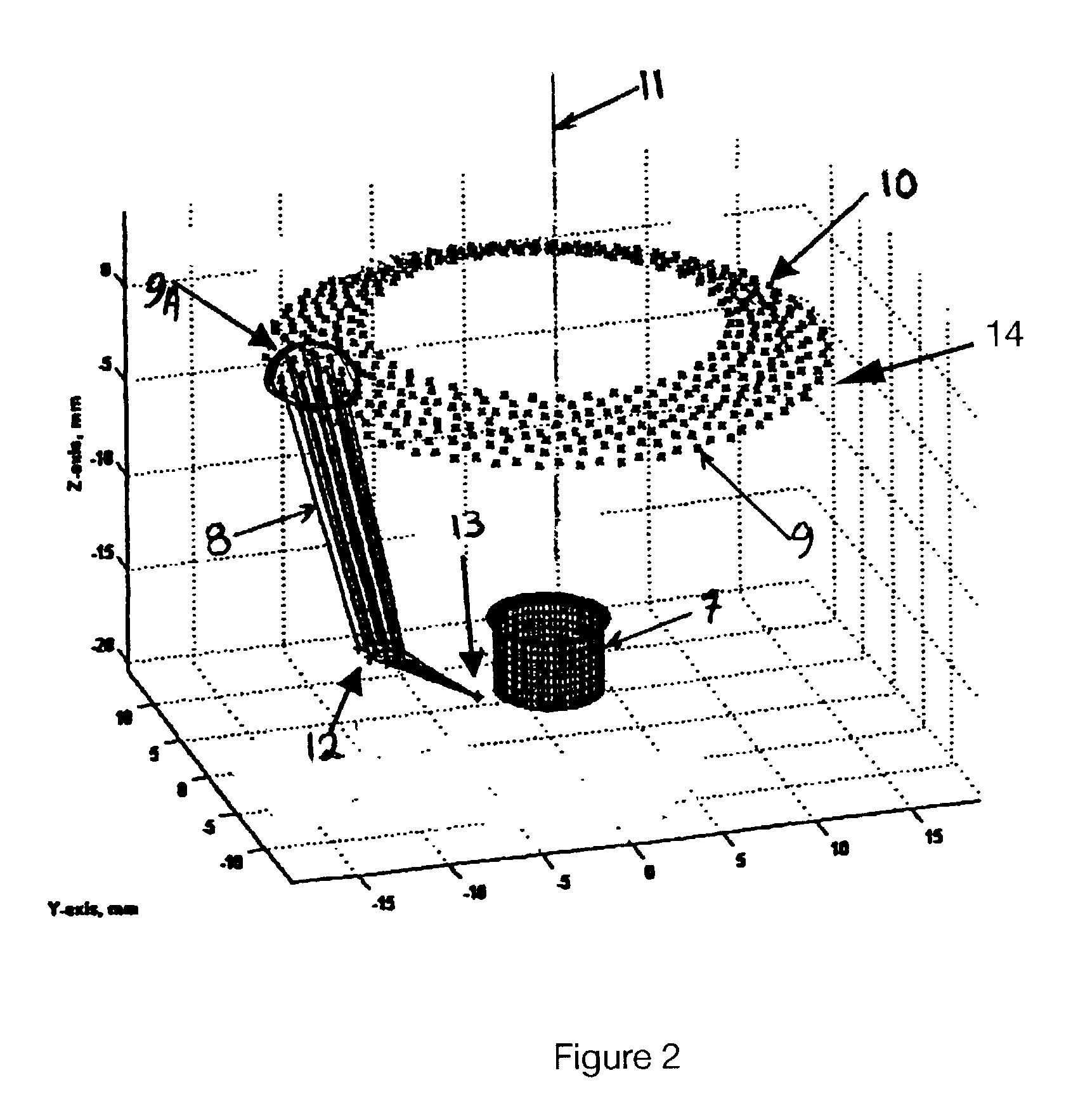
Scanning Using Phased Array Beams from Conic Surface

[0053]An angled beam is required in order to direct the ultrasonic beam under the fastener head 6 towards the fastener hole circumference 7 at the faying surface ⅔ interface. Phased array (PA) ultrasonic beams, as typified by beam 8, are preferably generated from a number of elements 9, typically piezoelectric crystals, distributed over a conic surface 10 that surrounds from above (i.e., looking down) a fastener opening placed beneath ...


PUM

PropertyMeasurementUnit
outer circumferenceaaaaaaaaaa
diameteraaaaaaaaaa
diameteraaaaaaaaaa

Abstract

An ultrasonic probe suited for testing the integrity of sheet metal surfaces around fastener openings is provided with means to center the probe over such openings. Both a mechanical centering rod and an electronic display assist the user in centering such probe. Once positioned within tolerance limits, phased array ultrasonic beams search for defects within the metal surfaces, allowing for residual offsets in the centering of the probe. Also described are test fixtures for calibrating the probe.

Description

FIELD OF THE INVENTION[0001]This invention relates to the non-destructive testing of materials surrounding fastener holes using ultrasonic phased arrays. More particularly it relates to a device for positioning a testing assembly over fastener holes and the detection of corrosion and material defects in the materials surrounding such fastener holes. The invention is particularly useful for testing material surrounding fastener openings present in the skin of aircraft.BACKGROUND TO THE INVENTION[0002]There has long been a requirement to detect small cracks and defects present on the faying surfaces of aircraft wing skin material present around fastener holes formed therein. This procedure is carried out with the fastener installed in the fastener opening. Aircraft fastener holes are prone to developing cracks that can propagate and result in serious structural failure.[0003]The current system has been in service for many years, but is now obsolescent and no longer maintainable. Its d...

Claims


Application Information

Patent Timeline
Patent Type & Authority Patents(United States)
IPC IPC(8): G01N29/07G01N29/06G01N29/26
CPCG01N29/0609G01N29/0645G01N29/262G01N2291/044G01N2291/106
Inventor MOLES, MICHAELDUPUIS, OLIVIERCANCRE, FABRICEHERZOG, PAMELAMILLER, JAMES TEDHATMAKER, JAMIE
Owner R D TECH
Why Eureka
Try Eureka