Method and apparatus for testing hollow pieces for impermeability

a technology of impermeability and hollow pieces, applied in the direction of fluid-tightness measurement, structural/machine measurement, instruments, etc., can solve the problems of reducing the test time, unable to conduct useful measurements, and unable to achieve useful measurements, so as to accelerate the achieving of temperature equilibrium and reduce the test time

Inactive Publication Date: 2001-08-23
MESSMANN ANNEMARIE
View PDF0 Cites 9 Cited by
  • Summary
  • Abstract
  • Description
  • Claims
  • Application Information

AI Technical Summary

Benefits of technology

[0004] It is an object of the present invention to provide a class-specific method that accelerates the achieving of the temperature equilibrium, to reduce the testing time in fixed-cycle manufacturing; in addition, it is an object of the present invention to provide a class-specific apparatus for implementing the method that allows safe and undisturbed vacuum testing even in connection with short fixed-cycle times.

Problems solved by technology

These conclusions are unreliable, however, if the internal pressure inside the test piece changes due to temperature variations after the suction is discontinued.
Therefore, conducting a useful measurement is only possible once a stationary equilibrium with regard to the temperature has been reached.
Using methods of this kind is particularly disadvantageous in instances of fixed-cycle manufacturing because the required waiting time period for achieving the temperature equilibrium is too long.
Another delay is caused by the evaporation of the water remaining in the pores which causes a cooling of the (rest) air content inside the test piece whereby a drop in pressure occurs which simulates an impermeability that does not in fact exist.

Method used


Image

  • Method and apparatus for testing hollow pieces for impermeability
  • Method and apparatus for testing hollow pieces for impermeability

Examples


Embodiment Construction

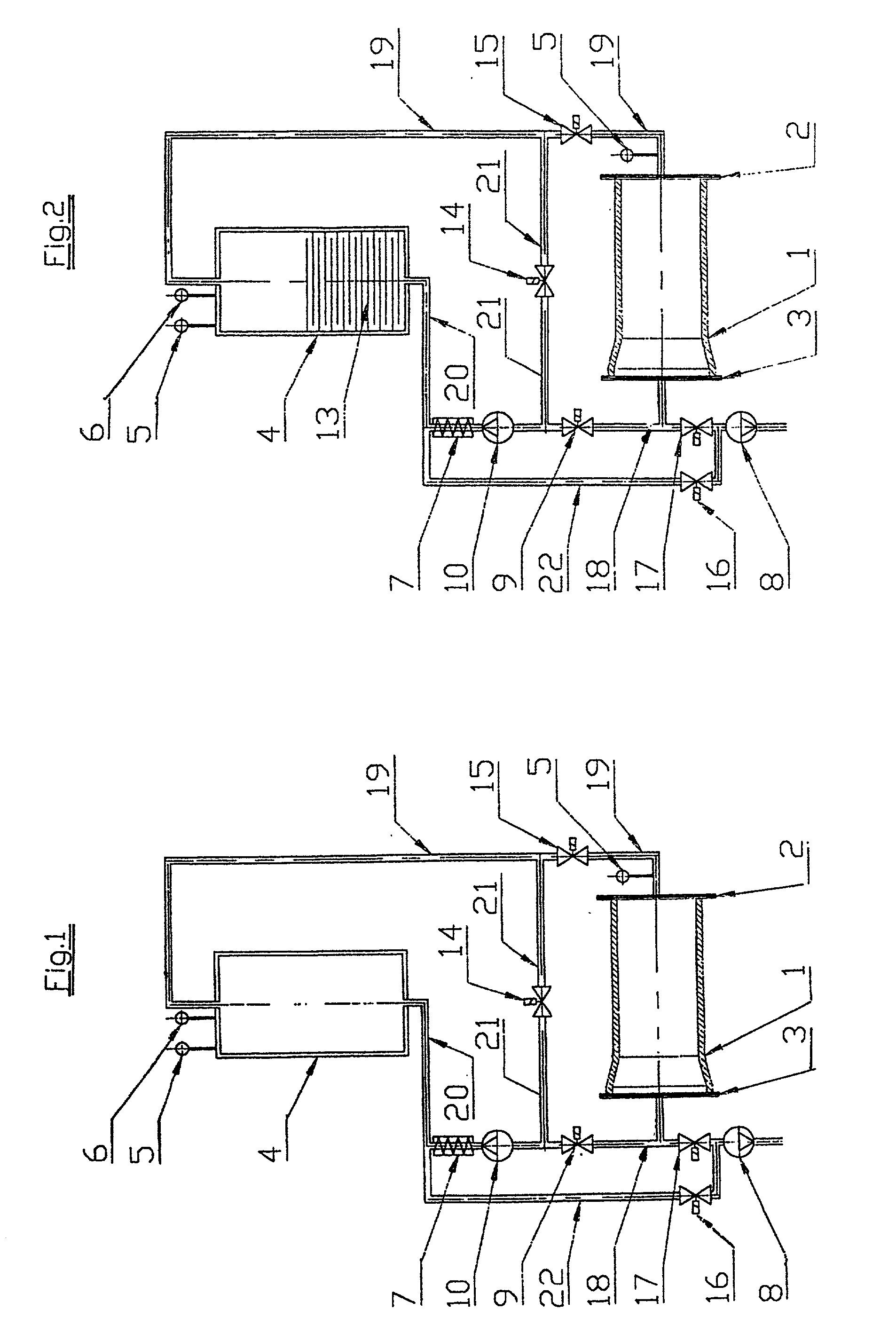
[0032] FIG. 1 shows the test piece 1, in particular a concrete pipe, that is clamped between the end plates 2 and 3 for the purpose of an impermeability test. It goes without saying that these end plates 2 and 3 are part of a whole testing construct (which is not shown here in more detail). The testing construct can also be set up to provide for examination of the test pieces 1 at fixed cycles, with the test pieces resting on a transport device and being transported through the testing construct that is designed as a testing station and as a part of the manufacturing process. The front plate 3 can be attached to a vacuum pump 8 via a tab line that is inserted into the connecting line 18. The vacuum pump 8 is suitable for adjusting the desired or required testing pressure inside the test piece 1. After the desired or required vacuum has been reached, a valve 17 is closed, thereby interrupting the connection between test piece 1 and vacuum pump 8. Any permeability in the walls of the ...


PUM

PropertyMeasurementUnit
impermeabilityaaaaaaaaaa
pressureaaaaaaaaaa
temperatureaaaaaaaaaa

Abstract

The impermeability of a test piece, e.g., a pipe made of concrete, clay, stoneware, etc., is tested using negative pressure air. Air in a compensation tank is maintained at negative pressure and also at a temperature that correspond to the temperature of the inside wall of the test piece. Then, the test piece, sealed on both ends, has a negative pressure is generated therein that corresponds to the negative pressure inside the compensation tank. Subsequently, the air inside the test piece is replaced with the temperature-controlled air from inside the compensation tank, and then the negative pressure inside the test piece is adjusted to a predetermined testing level. The progression of the negative pressure over a time period in the test piece is monitored. If the measured negative pressure drops below a prescribed tolerance limit, the pipe is considered too leaky.

Description

[0001] The invention relates to a method for testing hollow pieces, such as pipes etc. made of concrete, stoneware, casting etc, in terms of their impermeability using a vacuum testing apparatus. Also, the invention relates to an apparatus for implementing the method, consisting of a support for the test piece and a medium for scaling the test piece on both sides. In particular, one of the sealing media is connected with a vacuum pump as well as with instruments for measuring the negative pressure.[0002] The invention relies on known testing procedures for pipes made of stoneware, clay, concrete or similar porous materials. These procedures provide that both ends of the pipe are closed off with testing plates equipped with seals. If a negative pressure is created inside the test piece, that is sealed off on both sides, using the connected vacuum pump, it is possible to draw conclusions as to the grade of impermeability of the test piece based on the vacuum drop after the suction has...

Claims


Application Information

Patent Timeline
Patent Type & Authority Applications(United States)
IPC IPC(8): G01M3/28
CPCG01M3/2846
Inventor MESSMANN, MARTIN
Owner MESSMANN ANNEMARIE
Why Eureka
Try Eureka