
Flame sensor for a burner

a sensor and burner technology, applied in the field of flame sensor for burners, can solve the problems of unintended termination of the burner or heater operation, inconvenient termination of the fuel flow, and disrupting the integrity of the signal being passed to the amplifier by the sensor

Inactive Publication Date: 2008-02-05
INT THERMAL INVESTMENTS
View PDF6 Cites 26 Cited by
  • Summary
  • Abstract
  • Description
  • Claims
  • Application Information

AI Technical Summary

Problems solved by technology

However, it is inconvenient to terminate the fuel flow if the flame is present and the burner is working properly.
The termination of the fuel flow causes termination of the operation of the burner or heater unintendedly if the flame sensor sends an incorrect signal to the control panel.
One reason for unintended burner shutdown is signal contamination of the signal from the flame sensor, Since the power of the signal previously sent to the amplifier is quite small, in the range of 50 mv to 200 mv, and since the amplifier was located some distance from the sensor, any noise caused by common mode radiation or other RF signals could disrupt the integrity of the signal being passed to the amplifier by the sensor.
This causes incorrect information to be read by the microcontroller with the result that the heater could be inadvertently shut down or, alternatively, the heater may continue to run in a flame out condition.
Both scenarios are not desirable.
This leads to a decreased reading sensitivity of the pulsed signal generated by the photodiode of the flame sensor.
The components of the heater, however, generates noise and this noise can produce a signal which is similar to the signal generated by the photo diode when a flame is present.
Thus, the flame sensor circuit may incorrectly signal that a flame is present.

Method used


Image

  • Flame sensor for a burner
  • Flame sensor for a burner
  • Flame sensor for a burner

Examples


Embodiment Construction

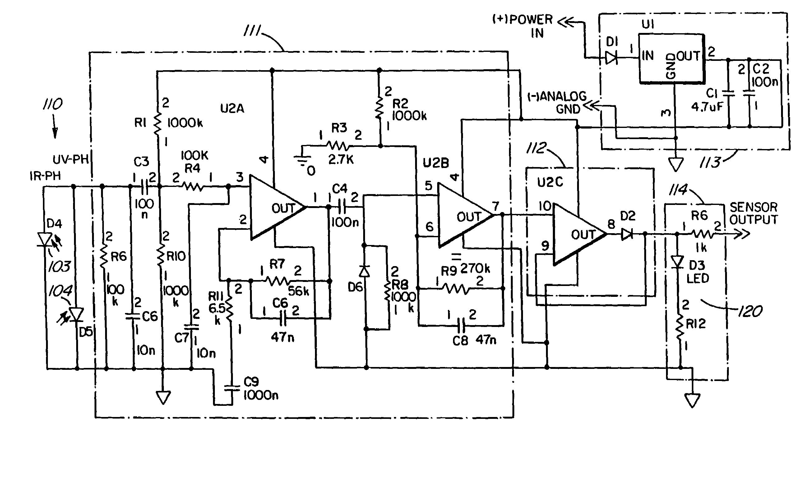
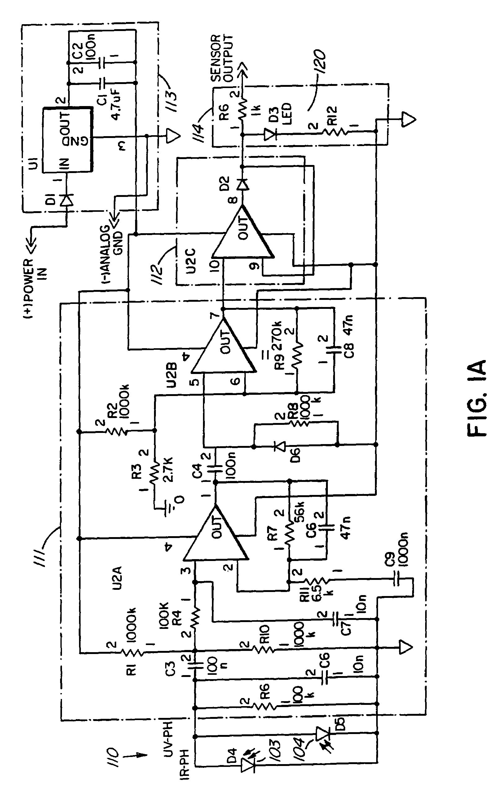
[0023]Referring now to the drawings, a powered multifuel burner is generally illustrated at 100 in FIG. 7. An infrared type burner 101 has a flame 105 (FIG. 6) generated within the cylinder 106 of the burner 101 by way of an air aspirated nozzle (not shown) which uses a venturi effect to draw fuel into the nozzle. Combustion takes place outside the nozzle but within the cylinder 106. The flame sensor 110 is located generally at 102 as illustrated in FIG. 6.

[0024]The flame sensor 110 may include either an infrared sensor or an ultraviolet sensor or, alternatively, a combination of an infrared and ultraviolet sensor. Each or both of the sensors 103 are positioned in the housing 121 (FIG. 4A) to sense the visible infrared and ultraviolet radiation produced by the combustion flame. The sensors 103 selected for the particular application will depend on the flame being produced within the burner 100. If, for example, the flame burns with an orange patina, the primary sensor will be infrar...


PUM

PropertyMeasurementUnit
voltageaaaaaaaaaa
voltageaaaaaaaaaa
voltageaaaaaaaaaa

Abstract

A flame sensor circuit is used to sense the presence or absence of a flame in a burner. A first sensor generates a first intensity signal which is proportional to the light intensity of the flame in the burner. A second sensor generates a second signal produced by the flicker of the flame. The presence of both the first and second signals is sensed and if both are present, an output signal is generated to indicate the presence of the flame in the burner.

Description

CROSS-REFERENCE TO RELATED APPLICATION[0001]This is a continuation-in-part of application Ser. No. 10 / 441,929 filed May 19, 2003 now abandoned and entitled IMPROVED FLAME SENSOR.INTRODUCTION[0002]This invention relates to a flame sensor and, more particularly, to a flame sensor which senses the presence of a flame within a burner and which flame sensor produces two signals to verify the presence of the flame within the burner.BACKGROUND OF THE INVENTION[0003]Flame sensors are used to sense the presence or absence of a flame in a heater or burner, for example, or other apparatus. The heater or burner may be used to heat water or ambient air and the fuel used may be one of several different types.[0004]In the event the flame is extinguished, although not deliberately so, the sensor is adapted to sense the absence of the flame. The flame can be extinguished, for example, by fuel starvation or other malfunction. After sensing the extinguishing of the flame, the sensor or its related cir...

Claims


Application Information

Patent Timeline
Patent Type & Authority Patents(United States)
IPC IPC(8): G08B17/12F23D14/72F23N5/24G01J5/00
CPCF23D14/725F23N5/242F23N2029/04F23N2029/08G01J5/0014F23N2229/04F23N2229/08
Inventor KIAROSTAMI, NADER
Owner INT THERMAL INVESTMENTS
Learn More