Pneumatic nail gun

a nail gun and pneumatic technology, applied in the direction of nailing tools, servomotor components, servomotors, etc., can solve the problems of not continuously guiding compressed air therein and maintaining a high pressure, affecting the speed and efficiency of nailing, and not ensuring the repositioning process of the nailing piston, so as to improve the operating facility simplify the distribution of the nailing gun, and reduce the cos

Inactive Publication Date: 2008-02-05
DE POAN PNEUMATIC
View PDF25 Cites 8 Cited by
  • Summary
  • Abstract
  • Description
  • Claims
  • Application Information

AI Technical Summary

Benefits of technology

[0009]The pneumatic nail gun has a main passage to substitute of the return passage for continuously guiding the compressed air to drive the hitting piston to upwardly move to reposit. Moreover, this pneumatic nail gun employs the main passage and a bottom valve to substitute of the conventional valve mechanisms and the passages, in which, the main passage and the bottom valve are both disposed at a peripheral portion of the nail gun for simplifying the distribution of the nail gun, so as to improve the operating facility of the nail gun and lower the cost thereof.

Problems solved by technology

However, the return passage can only collect compressed air during the hitting piston downwardly moving to hitting nails, which can not continuously guiding compressed air thereinto and maintaining a high pressure therein.
Therefore, the pushing force generated by the limited compressed air in the return passage may not ensure the hitting piston having a stable reposition process.
During the process of continuously hitting nails, slower and unstable reposition of the hitting piston may impact the speed and efficiency of hitting nails.
However, the valve mechanisms are disposed in the gun body far away from the cylinder, it request that the gun body has a larger space and complicated passages to realize introducing the high pressure air into the bottom chamber to drive the hitting piston upwardly move to reposit.
Therefore, the nail gun has a high manufacturing cost and complicated air flow passages.

Method used


Image

  • Pneumatic nail gun
  • Pneumatic nail gun
  • Pneumatic nail gun

Examples


Embodiment Construction

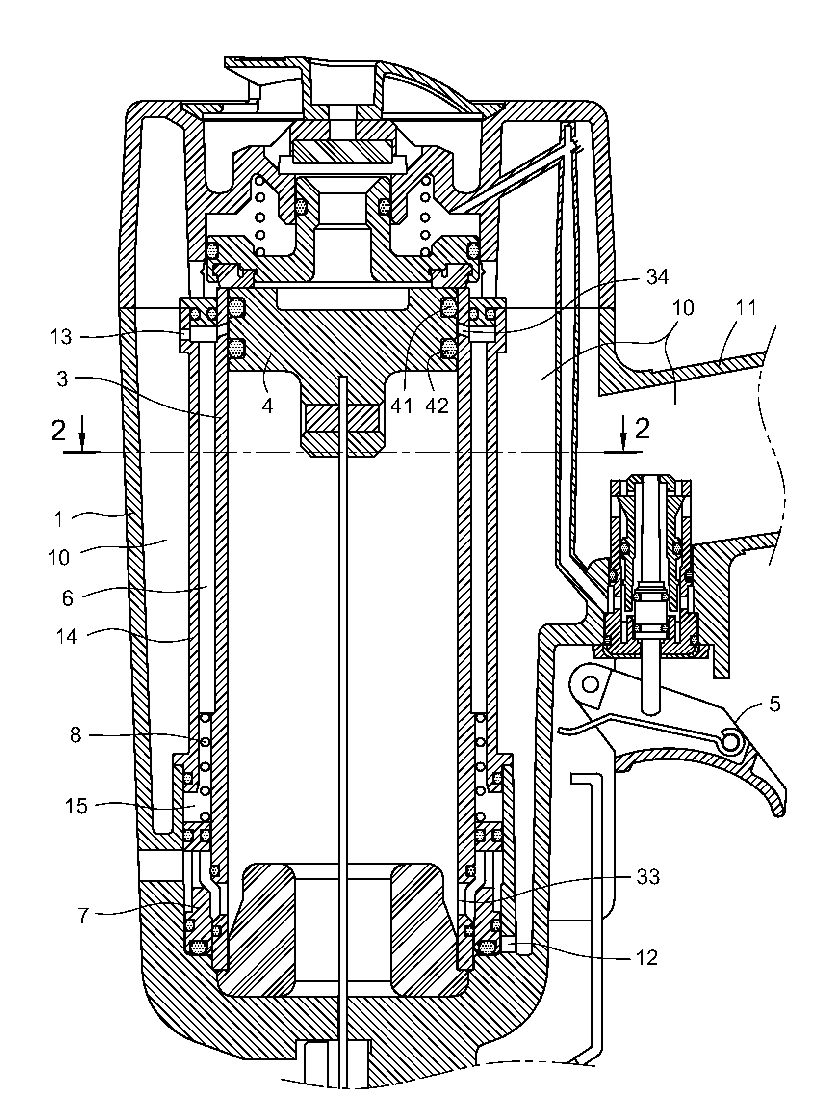
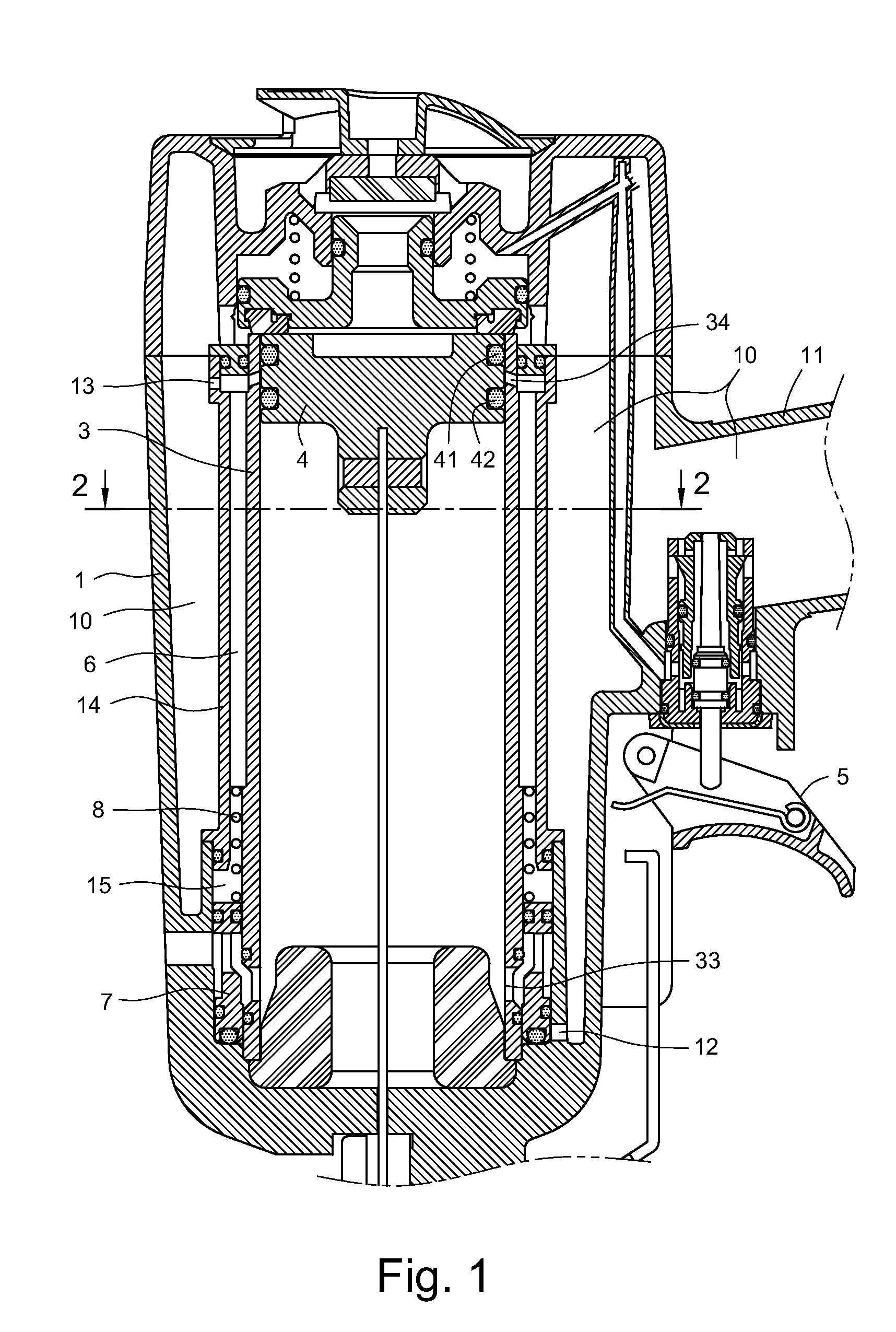
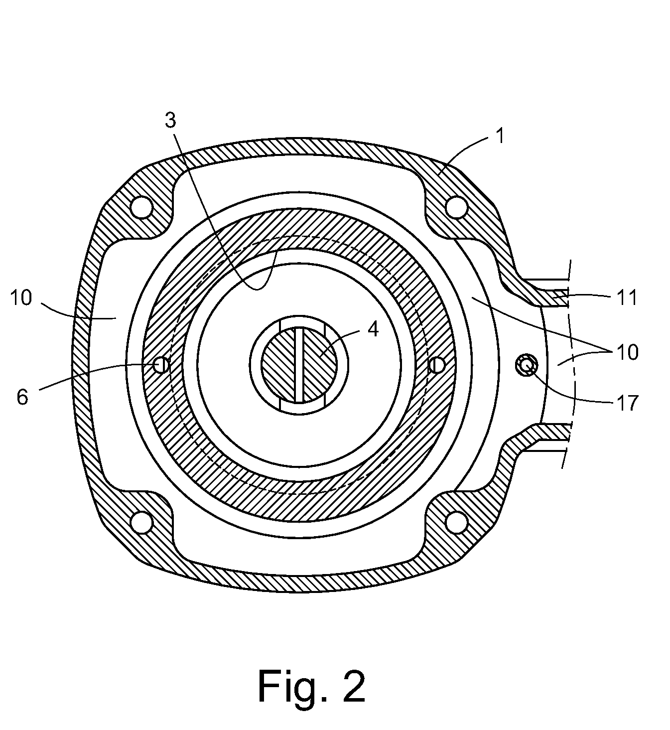
[0019]Referring to FIGS. 1 to 6, a pneumatic nail gun according to a first embodiment of the present invention is shown. The pneumatic nail gun has a gun body 1, an immovable cylinder 3, a hitting piston 4 disposed in the immovable cylinder 3, a main air housing 10 disposed in the nail gun, at least one main air flow passage 6, and a bottom valve 7.

[0020]The hitting piston 4 includes at least two air tight rings 41 and 42, which can divide the cylinder 3 into a top chamber 31 and a bottom chamber 32 when the hitting piston 4 move downward to hit nails or move upward to reposit.

[0021]The main air housing 10 is disposed between a handle 11 of the nail gun and the peripheral portion of the cylinder 3 for gathering continuously introducing high pressure air from atmosphere via a free end of the handle 11. The main air housing 10 further includes a trigger 5 disposed at one end of the main air housing 10 for driving the hitting piston 4 downwardly move to hit nails and upwardly reposit.

[...


PUM


Abstract

A pneumatic nail gun includes a gun body having a cylinder therein; a hitting piston disposed in the cylinder; a main air housing collecting high pressure air; a trigger at one end of the main air housing; a main passage disposed at a peripheral portion of the cylinder, the main passage being connecting with the main air housing for gathering high pressure air therein; and a bottom valve disposed at a bottom peripheral portion of the cylinder, the bottom valve being driven to upwardly move for continuously guiding high pressure air into the bottom chamber to drive the hitting piston upwardly move to reposit when the trigger is released. When the high pressure air in the main passage is recharged, the bottom valve is driven by the high pressure air gathered in the main passage to move downward to reposit after the hitting piston being reposited.

Description

BACKGROUND[0001]The present invention relates to pneumatic nail guns, and particularly to a pneumatic nail gun having a main passage and a bottom valve disposed at a peripheral portion of a fixed cylinder of the nail gun, for continuously guiding compressed high pressure air to drive a hitting piston of the nail gun upwardly reposit.[0002]The pneumatic nail gun generally utilizes a compressed high pressure air to drive nails to punch, which is a gun-shaped pneumatic tool, and has been widely used in nailing woodworkers.[0003]A typical pneumatic nail gun has a gun body, and a fixed or a moveable cylinder disposed in the gun body, which is used to control the compressed high pressure air to drive a piston in the cylinder to downwardly hit nails as well as upwardly reposit.[0004]The related arts, such as U.S. Pat. No. 6,533,156, U.S. Pat. No. 6,779,699 and U.S. Pat. No. 6,006,975 respectively disclosed a typical pneumatic nail gun employing a fixed cylinder. The pneumatic nail gun incl...

Claims


Application Information

Patent Timeline
Patent Type & Authority Patents(United States)
IPC IPC(8): B25C1/04
CPCB25C1/041
Inventor WEN, WAN-FU
Owner DE POAN PNEUMATIC
Why Eureka
Try Eureka