Optical disk device having mirror in micro electrical mechanical system
a micro electrical mechanical and optical disk technology, applied in the direction of digital signal error detection/correction, instruments, recording signal processing, etc., can solve the problem of inability to enhance the gain of tracking control, the tracking capability of the information track 3 of the optical storage medium 3 can be improved, and the effect of accurately tracked/traced
- Summary
- Abstract
- Description
- Claims
- Application Information
AI Technical Summary
Benefits of technology
Problems solved by technology
Method used
Image
Examples
first embodiment
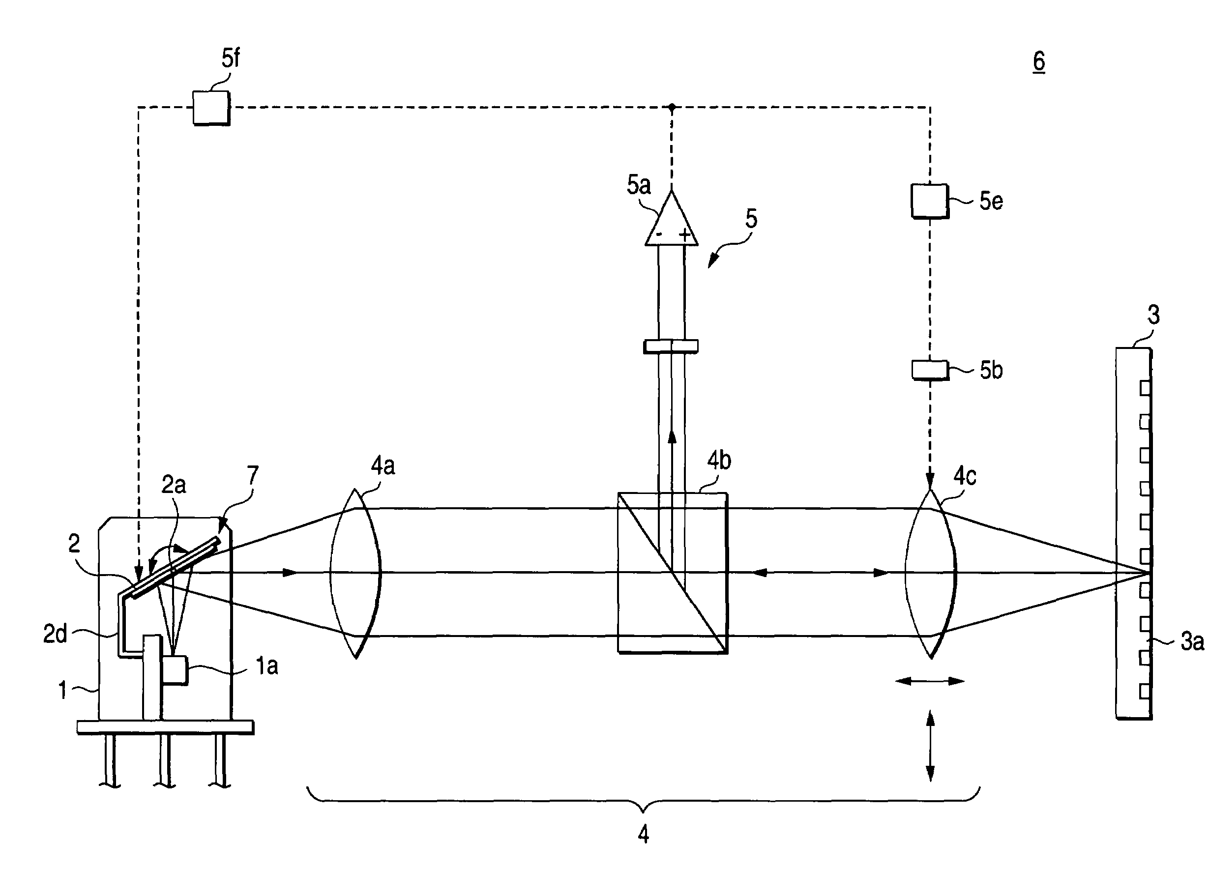
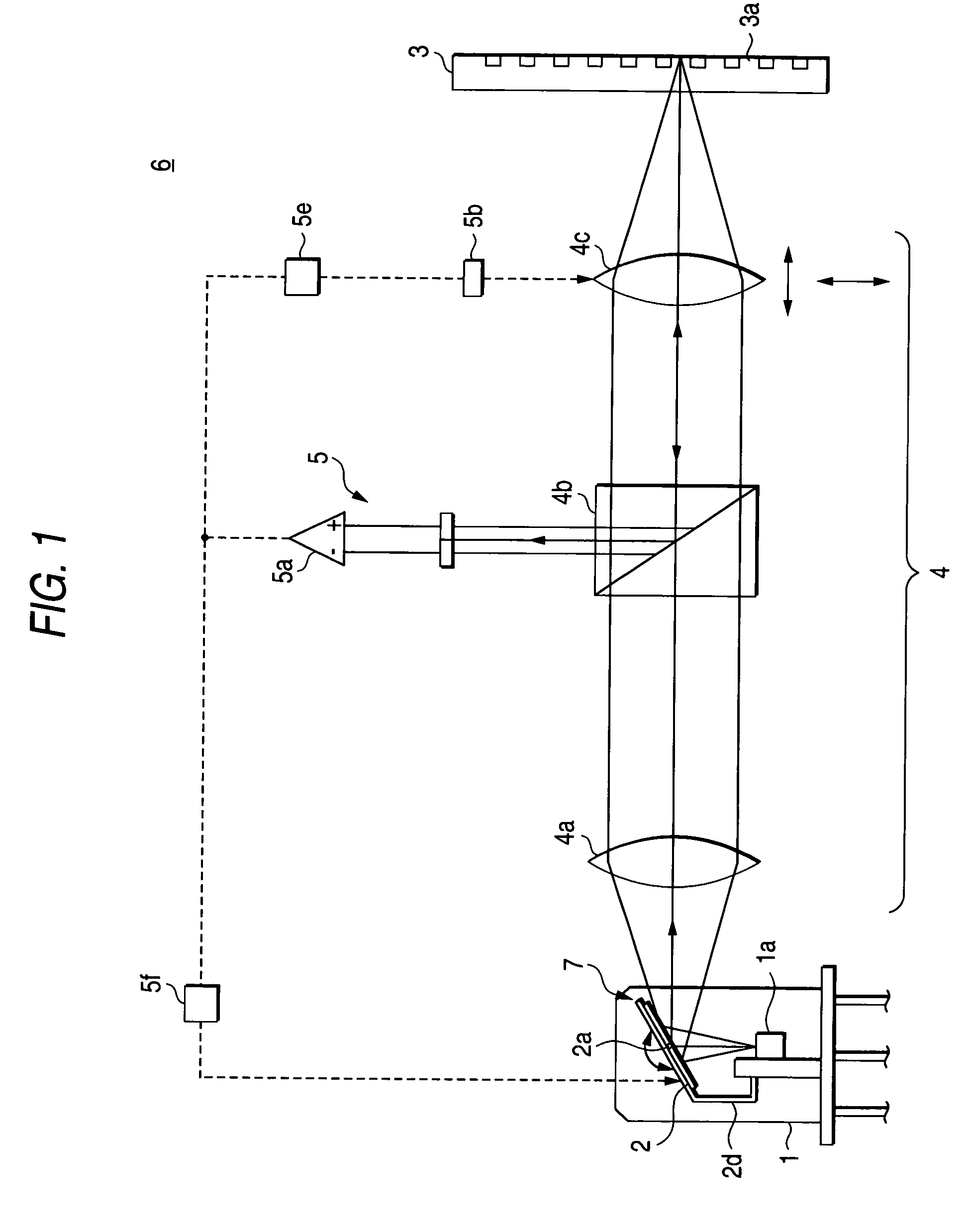
[0027]As shown in FIG. 1, an optical disk device 6 includes a movable mirror 2 for deflecting the laser beam emitted from a laser light source 1a, an optical head 4 for focusing the deflected laser beam on an optical recording medium (optical disk 3), and a derive control section 5 for detecting the laser beam reflected from the optical recording medium 3 and tracking-controlling the optical head 4 and the movable mirror 2 on the basis of the laser beam thus detected.
[0028]The movable mirror 2, as shown in FIGS. 1 and 2, is included in a micro electrical mechanical system (MEMS). The MEMS 7 including the movable mirror 2 is housed within a package 1 which accommodates the laser light source 1a.
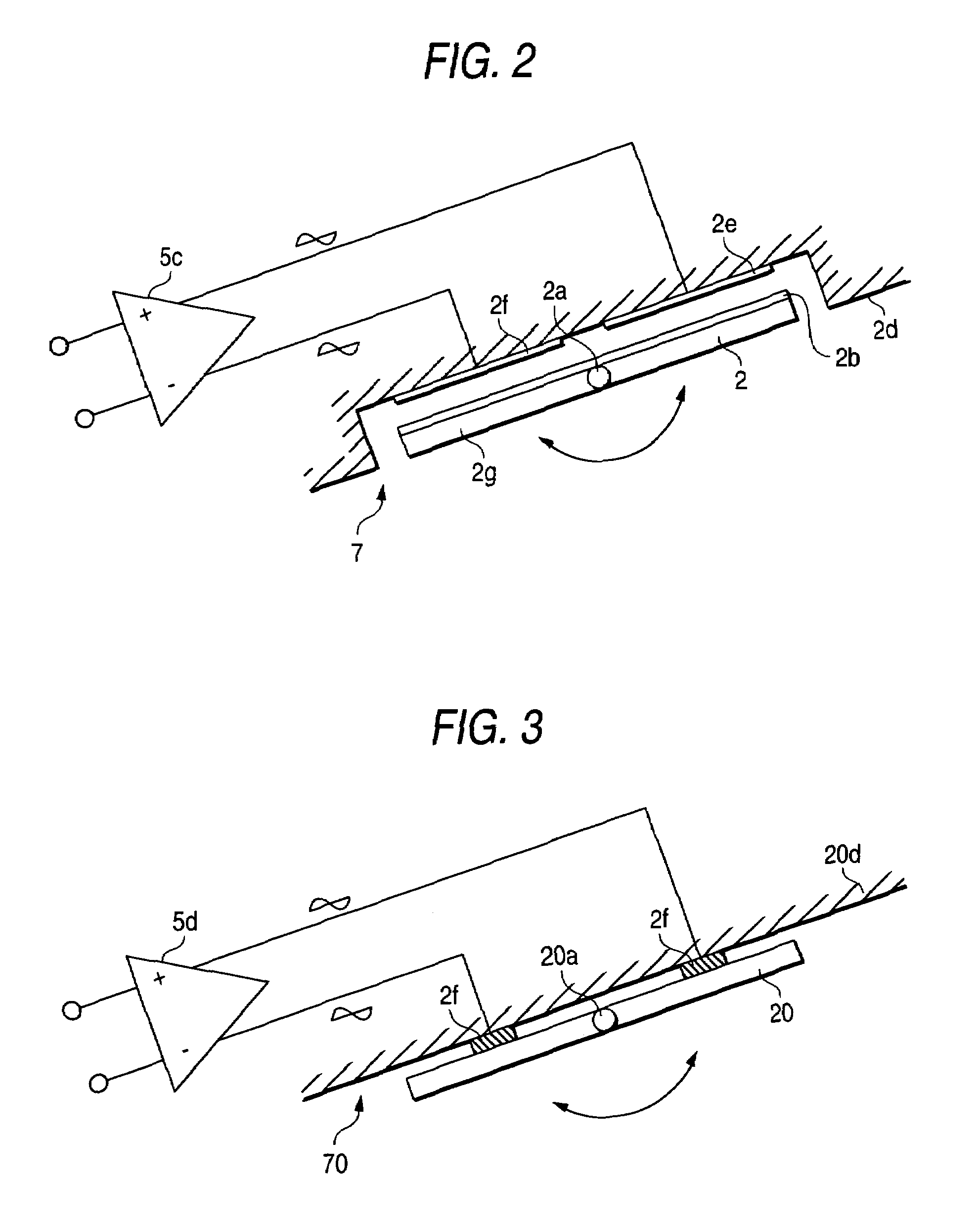
[0029]The MEMS 7 includes the movable mirror 2 having a pair of rotary shafts 2a attached to side portions 2g of the mirror 2. The mirror 2 is formed in the shape of a square in plan view. The MEMS 7 further includes a film 2b put on an upper surface of the movable mirror 2, and two films 2e ...
second embodiment
[0040]The optical disk according to a second embodiment is different from the first embodiment in only the configuration of the MEMS, and has almost the same elements as in the first embodiment. Therefore, the other elements than the MEMS are not described here.
[0041]As shown in FIGS. 1 and 3, a movable mirror 20 is included in a MEMS 70 as in the first embodiment. The MEMS 70 including the movable mirror 2 is housed within the package 1 which accommodates the laser light source 1a.
[0042]As in the first embodiment, the MEMS 70 includes the movable mirror 20 equipped with a pair of rotary shaft 20a, two piezoelectric elements 2f, 2f attached to a substrate 20d located above the movable mirror 20. The two piezoelectric elements 2f, 2f are made of e.g. copolymer of PVDF (polyvinylidene fluoride) and ethylene trifluoride. The two piezoelectric elements 2f, 2f are put on the substrate 2d to be apart from each other by a predetermined distance with respect to the rotary shafts 20a. The t...
third embodiment
[0047]The optical disk according to a third embodiment is different from the first and second embodiment in only the configuration of the MEMS, and has almost the same elements as in the first and second embodiment. Therefore, the other elements than the MEMS are not described here.
[0048]As shown in FIGS. 1 and 4, a movable mirror 78 is included in a MEMS 77, like the first and the second embodiment. The MEMS 77 including the movable mirror 78 is housed within the package 1 which accommodates the laser light source 1a.
[0049]The MEMS 77 includes a substrate 79 made of a square silicon wafer, a mirror section 79a formed on the substrate 79, two permanent magnets 80 to lie the substrate 79 therebetween, rotary shafts 82a and 82b formed on opposite sides 79b of the substrate 79 respectively, which make the substrate 79 rotatable within a predetermined angle, and a coil section 81 formed on the substrate 79. When a current is passed through the coil section 81, a running torque is gener...
PUM
| Property | Measurement | Unit |
|---|---|---|
| thickness | aaaaa | aaaaa |
| width | aaaaa | aaaaa |
| thick | aaaaa | aaaaa |
Abstract
Description
Claims
Application Information
 - R&D
- Intellectual Property
- Life Sciences
- Materials
- Tech Scout
- Unparalleled Data Quality
- Higher Quality Content
- 60% Fewer Hallucinations
Browse by: Latest US Patents, China's latest patents, Technical Efficacy Thesaurus, Application Domain, Technology Topic, Popular Technical Reports.
© 2025 PatSnap. All rights reserved.Legal|Privacy policy|Modern Slavery Act Transparency Statement|Sitemap|About US| Contact US: help@patsnap.com


