
Gait generation device for legged mobile robot

a mobile robot and generation device technology, applied in the direction of electric programme control, program control, instruments, etc., can solve problems such as errors

Active Publication Date: 2008-01-15
HONDA MOTOR CO LTD
View PDF17 Cites 16 Cited by
  • Summary
  • Abstract
  • Description
  • Claims
  • Application Information

AI Technical Summary

Benefits of technology

The present invention provides a gait generation device for legged mobile robots that can generate a desired gait by setting an allowable range of a limitation-target quantity and determining a provisional instantaneous value of the desired movement. The device includes a model calculating means that inputs the provisional instantaneous value of the desired movement to a dynamics model to determine a model floor reaction force instantaneous value. The device can correct the provisional instantaneous value of the desired movement to ensure that the limitation-target quantity falls within the allowable range. The invention allows for the generation of a variety of desired gaits, including normal walking, running, and walking on a floor of low friction coefficient. The dynamics model used is preferably a high-approximation precision model. The device can stabilize the error of the provisional instantaneous value and reduce it to a minimum while keeping the limitation-target quantity within the allowable range.

Problems solved by technology

However, it is referred to as an error for the sake of convenience.

Method used


Image

  • Gait generation device for legged mobile robot
  • Gait generation device for legged mobile robot
  • Gait generation device for legged mobile robot

Examples


first embodiment

[0248]Now, details of the processings performed by the gait generation device 100 according to the present invention will be described more specifically.

[0249]The gait generation device 100 according to this embodiment generates sequentially a desired gait for one step from the landing of one leg 2 of the robot 1 to the landing of the other leg 2, (desired gait according to the definition (b″)). For example, in the case of generating the desired running gait shown in FIG. 5, the desired gait is generated sequentially from the start of a one-leg supporting period to the end of the following floating period (that is, the start of the next one-leg supporting period). Here, the desired gait to be newly generated is referred to as a “current time gait”, the next gait is referred to as a “next time gait”, and the desired gait after next is referred to as a “next but one gait”. In addition, the desired gait generated immediately before the current time gait is referred to as a “last time g...

second embodiment

[0637]Now, the present invention will be described. A correction method for a device according to the second embodiment is of a full model feed forward type. Furthermore, the method uses the inverse dynamics full model (inverse full model), doesn't correct the input of the simplified model gait and uses a perturbation model.

[0638]FIG. 50 is a functional block diagram for illustrating an operation of the device according to the second embodiment, specifically, the gait correction method in step S038 in the flowchart in FIG. 13. However, as in the first embodiment, a simplified model 200 shown in FIG. 50 is not simply a dynamics model but represents the process from steps S010 to S034 described above, that is, calculation (determination) of the simplified model gait's instantaneous values. Therefore, the sections following the simplified model 200 in FIG. 50 are associated with the processing in step S038. Of the functional sections shown in FIG. 50, same functional sections as those ...

fourth embodiment

[0754] the perturbation model 202 for correcting body horizontal positions and the perturbation model 203 for correcting body posture angles are used. In addition, two distributors 220 and 221 are used.

[0755]The distributors 220 and 221 are one-input two-output transfer blocks and determine one of the outputs according to the input (for example, determine one of the outputs by performing, on the input, a signal processing concerning frequency characteristics, dead-band characteristics, saturation characteristics or the like) and determine the other output in such a manner that the sum of the two outputs exactly or substantially agrees with the input.

[0756]The distributor 220 receives the body posture angle correcting moment Mr, which is the difference between the limited corrected desired floor reaction force's moment Mltd and the moment Mpf for stabilizing the perturbation model for correcting body horizontal positions (that is, output of the Mr calculator 214) and provides a body ...


PUM


Abstract

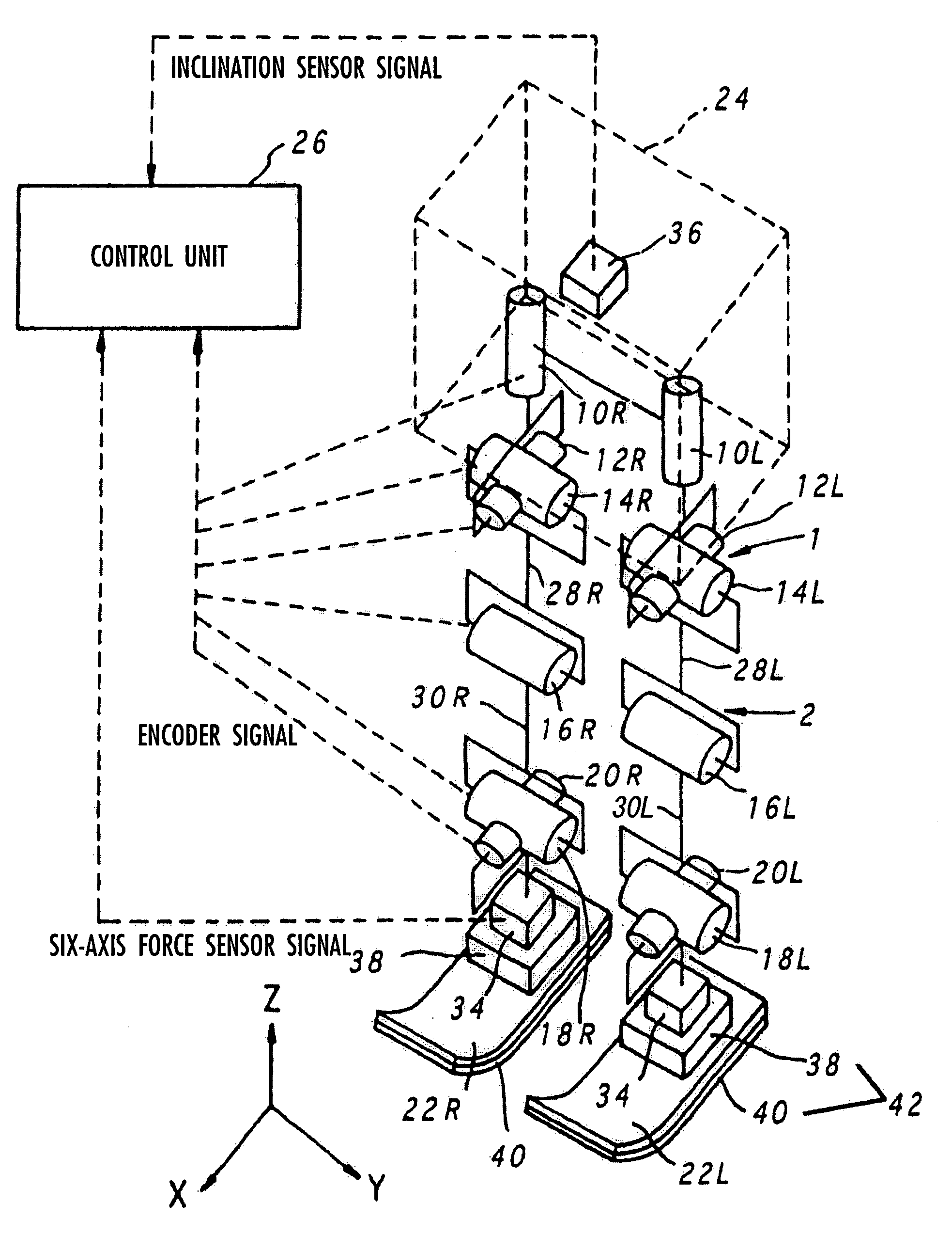
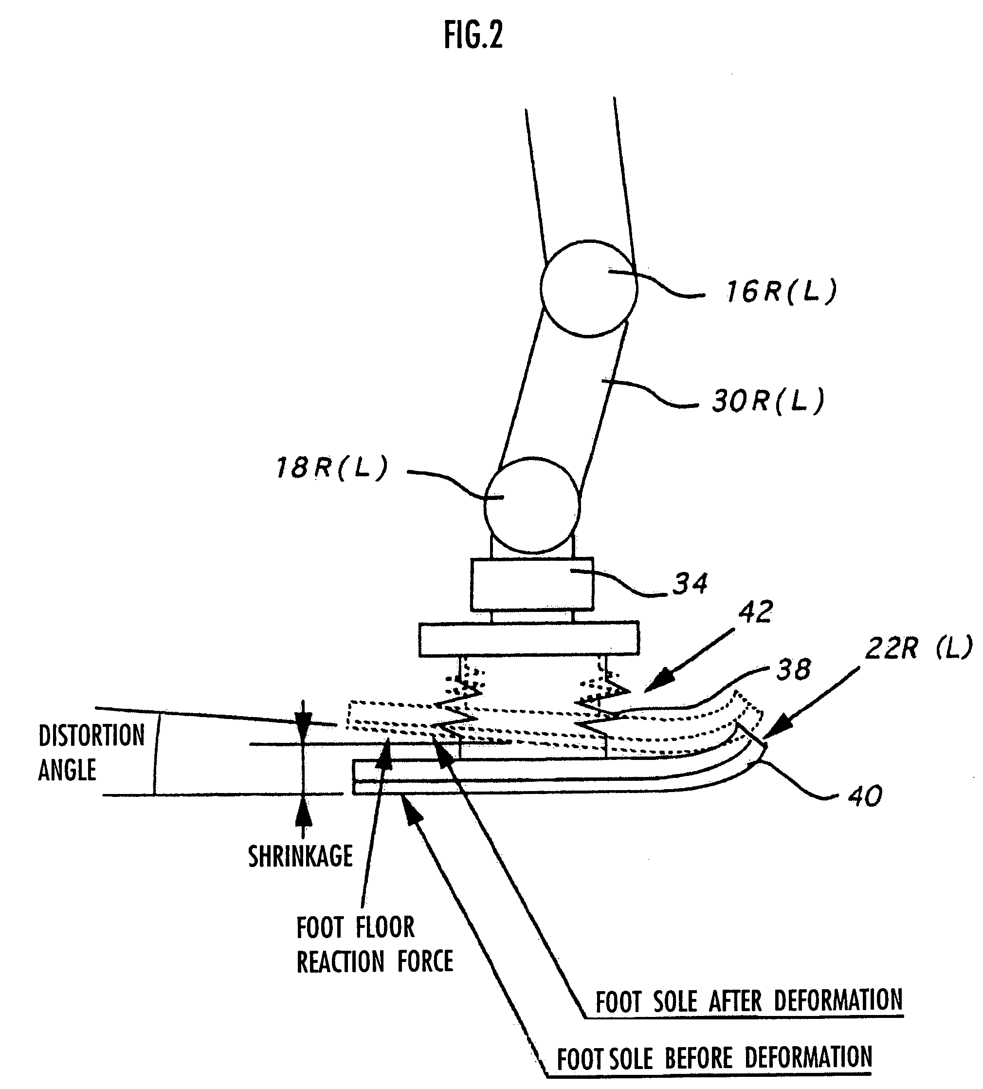
A gait generation device for setting a translation floor reaction force's horizontal component (component concerning a friction force) applied to a robot 1, a limitation-target quantity, such as a ZMP, and an allowable range, for determining at least a provisional instantaneous value of a desired floor reaction force and a provisional instantaneous value for a desired movement of the robot 1, that receives at least the provisional instantaneous value for the desired movement and determines a model floor reaction force instantaneous value with the aid of a dynamics model. Based on the difference between the model floor reaction force instantaneous value and the provisional instantaneous value of the desired floor reaction force or the allowable range of the limitation-target quantity, the provisional instantaneous value for the desired movement is corrected so that the limitation-target quantity falls within the allowable range and a dynamical equilibrium condition on the dynamics model is satisfied, thereby determining a desired instantaneous value.

Description

TECHNICAL FIELD[0001]The present invention relates to a gait generation device for a legged mobile robot.BACKGROUND ART[0002]In Japanese Patent Application No. 2000-352011, the applicants have proposed a technique of using a relatively simple robot dynamics model to generate in real time a flexible gait (referred to as an approximate gait, hereinafter) with which a robot can continuously move while approximately satisfying its dynamical equilibrium condition (i.e., without divergence).[0003]Furthermore, in Japanese Patent Application No. 2001-133621, there is proposed a technique of generating a gait that is corrected so as to precisely satisfy the dynamical equilibrium condition and substantially follow the approximate gait without divergence. A desired gait corrected is referred to as a corrected desired gait or a corrected gait, hereinafter.[0004]However, in Japanese Patent Application No. 2001-133621, a desired floor reaction force, which has been appropriately determined, is sh...

Claims


Application Information

Patent Timeline
Patent Type & Authority Patents(United States)
IPC IPC(8): G06F19/00B62D57/032
CPCB62D57/032B25J5/00B25J13/00
Inventor TAKENAKA, TORUMATSUMOTO, TAKASHIYOSHIIKE, TAKAHIDE
Owner HONDA MOTOR CO LTD
Learn More