Eureka AIR delivers breakthrough ideas for toughest innovation challenges, trusted by R&D personnel around the world.

Replica regulator with continuous output correction

a regulator and output correction technology, applied in the field of electronic circuits, can solve the problems of degrading load regulation, affecting the efficiency of the system,

Active Publication Date: 2008-01-15
MONTEREY RES LLC
View PDF13 Cites 53 Cited by
  • Summary
  • Abstract
  • Description
  • Claims
  • Application Information

AI Technical Summary

Benefits of technology

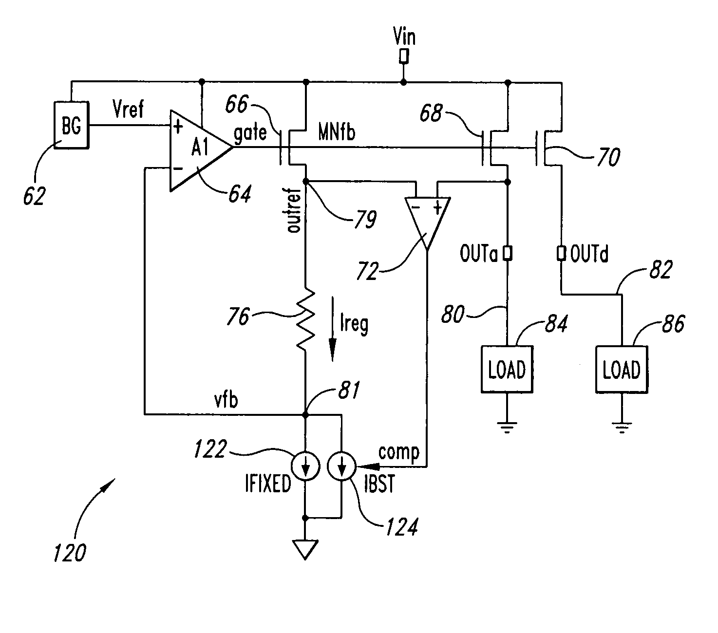
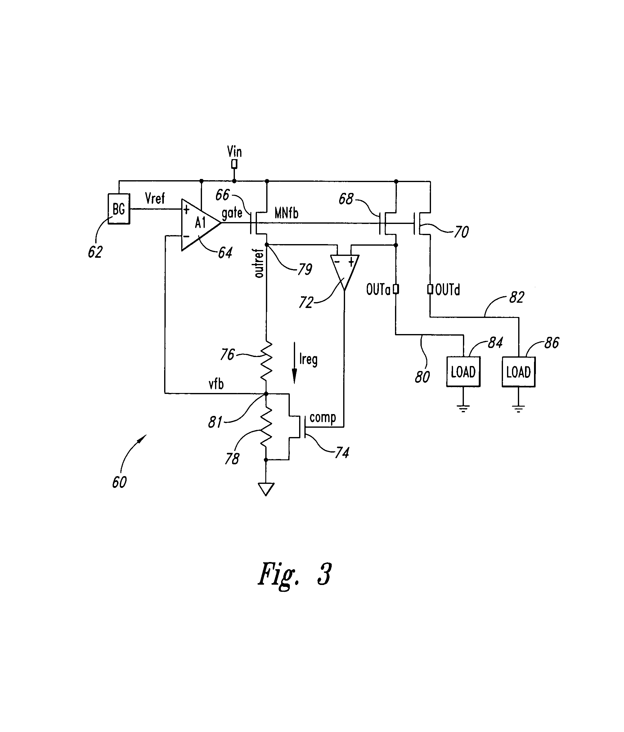
[0013]In accordance with another broad aspect of another embodiment of the present invention, disclosed herein is a regulator circuit. In one example, the regulator circuit may include a first amplifier providing an amplifier output signal, the first amplifier having at least a first input and a second input, the first input receiving a voltage reference signal; a first transistor receiving the amplifier output signal, the first transistor having a transistor output; at least one resistor coupled between the transistor output and the second input of the first amplifier and defining a feedback voltage signal node; a second transistor in parallel with the first

Problems solved by technology

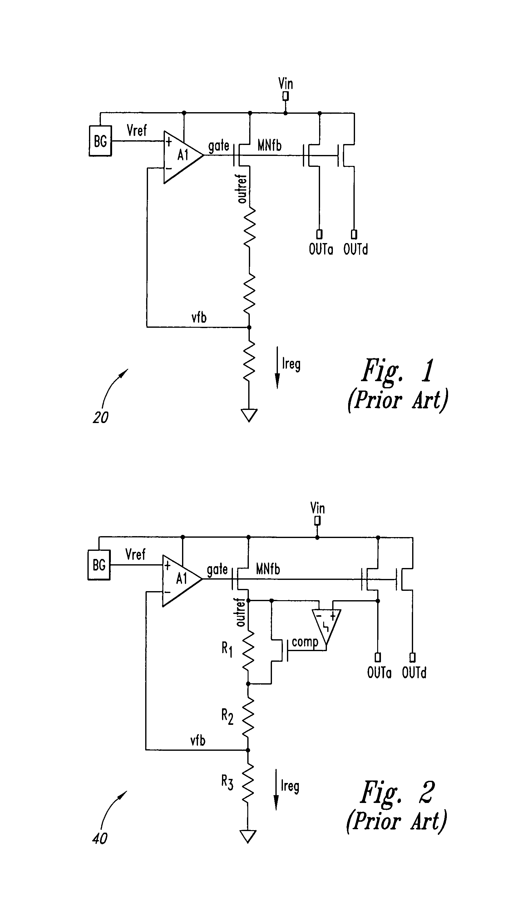
This conventional replica architecture 20 may suffer from poor load regulation, as no information about the output voltage is available to the regulator core.
The poor load regulations are worse at minimum input voltage levels and load current values.
However, this scenario will cause an abrupt change in output voltage with increasing load current, and will degrade load regulation.
However, these conventional replica regulator implementations 20, 40 can suffer from poor load regulation and poor peak load current capability.

Method used


Image

  • Replica regulator with continuous output correction
  • Replica regulator with continuous output correction
  • Replica regulator with continuous output correction

Examples


Embodiment Construction

[0024]Disclosed herein are various embodiments of a circuit for providing a regulated output signal. In one embodiment, a replica regulator is disclosed which has continuous current feedback, and a second control or feedback mechanism is provided to improve the robustness of the regulated output signal.

[0025]In one example, the regulator circuit continuously corrects for diminishing output voltage, with increasing output load current, by current feedback to regulator core, thereby providing load regulation due to this continuous correction.

[0026]The load regulation can be further adjusted by second loop gain and feedback amount. In one example, the second loop comprises a second operational-amplifier and transistor, which can enable the regulator circuit to supply large peak load current without increasing the standby current of the regulator core. Various embodiments of the present invention are disclosed herein.

[0027]FIG. 3 illustrates one embodiment of the present invention where...


PUM


Abstract

Circuits for regulating a voltage or current to a load(s). In one example, a circuit may include a first amplifier providing an amplifier output signal, the first amplifier having at least a first input and a second input, the first input receiving a voltage reference signal; a first transistor receiving the amplifier output signal, the first transistor having a transistor output; at least one resistor coupled between the transistor output and the second input of the first amplifier and defining a feedback voltage signal node; a second transistor in parallel with the first transistor, the second transistor receiving the amplifier output signal, the second transistor providing a regulated output signal of the circuit; a second amplifier receiving the output signal of the second transistor and the transistor output of the first transistor, the second amplifier providing a control signal; and a circuit element coupled between the feedback voltage signal node and ground, the circuit element receiving as a control the control signal of the second amplifier.

Description

CROSS REFERENCE TO RELATED APPLICATION[0001]This application claims priority under 35 U.S.C. 119(e) to U.S. Provisional Patent Application No. 60 / 639,009 entitled “Replica Regulator with Continuous Output Correction” filed Dec. 22, 2004, the disclosure of which is hereby incorporated by reference in its entirety.FIELD OF THE INVENTION[0002]The present invention relates generally to electronic circuits, and more particularly to regulator circuits.BACKGROUND OF THE INVENTION[0003]Regulator circuits are widely used in integrated circuit designs to provide an internal power supply or supply reference (such as a voltage or current) which, ideally, decouples the external applied power supply voltage (to the first order) as well as load on the supply pins of the chip[0004]A first conventional n-channel replica regulator 20 solution is shown in FIG. 1. The regulator 20 takes a voltage input, and provides two separate voltage outputs for analog and digital logic (outa and outd respectively)....

Claims


Application Information

Patent Timeline
IPC IPC(8): G05F3/16G05F3/20
CPCG05F1/46G05F1/577G05F1/575
Inventor MAHESHWARI, SANJEEVTAHERI, BABAK
Owner MONTEREY RES LLC
Why Eureka
Eureka Blog
Learn More