Rotary vane engine and thermodynamic cycle

a technology of thermodynamic cycle and rotary vane, which is applied in the direction of rotary piston engines, rotary or oscillating piston engines, jet propulsion plants, etc., can solve the problems of increasing the probability of engine failure, increasing the complexity of the system, and many rotary engines faced serious wear and sealing deficiencies, so as to increase the thermal efficiency and reduce the power input of the shaft. , the effect of high compression ratio

Inactive Publication Date: 2008-01-01
AKMANDOR IBRAHIM SINAN +1
View PDF26 Cites 16 Cited by
  • Summary
  • Abstract
  • Description
  • Claims
  • Application Information

AI Technical Summary

Benefits of technology

[0008]One of the objects of this invention, is to increase the thermal efficiency above levels reached by today's heat engines. This is achieved by implementing a longer power extraction phase (151eh, 151fh, 151gh) and by realising high compression ratios with less shaft power input, by processing the fluid through a smooth crescent shape constriction (72 and 49 and 53). Another object of the present invention is to decrease the wear. Wear is minimised through the incorporation of the pivot axle vane retention mechanism (138, 139, 150) and by providing an efficient oil lubrication. The operational and maintenance costs are also minimised, as maximum peak temperature is limited. All together, the present invention discloses an efficient, powerful, compact, simple and reliable heat engine.
[0009]For the compound engine configuration of the instant invention, rotary components and gas turbine engine components have been matched with each other. The objective is to combine the high efficiency and “no-stall” characteristics of internal combustion engines with the high mass flow, smaller size and lighter weight characteristics of the gas turbine engines. Another objective is to eliminate the long, heavy and cumbersome concentric shafts and reduction gears that are present in today's turbofan, turboprops and turbojet engines. By simplifying the mechanical links and by integrating low mass flow rotary components, the implementation of high efficiency reheat and intercooling systems have become extremely feasible.SUMMARY OF THE INVENTION
[0010]The solo configuration (FIGS. 1,2,3,4) of the invention relates to a rotary vane type machine comprising a compressor (10,19;46,48) and a turbine (36,43;57,59) housing, each having a crescent shape cavity. Each of these housing is receiving an eccentrically placed rotor (4,11,89,96,117) equipped by a radially movable single sliding vane (50,63) arranged in the rotor. The rotor receives a centrally placed pivot axle vane retention mechanism, which is comprised of a pin (139) and a pivot axle (150). The pin head fits into the vane centre socket. Both ends or tips (86,109) of the sliding vane (87,100,119,125) are extending radially outward and are in contact with the cycloidal inner surface of the housing peripheral (88,97) at all rotational angles. Within each housing, depending on the rotational position of the sliding vanes, forms a plurality of working chambers (49, 53, 60, 66, 72) each of the said chambers, delimited by the inner peripheral surface of the housing (48, 59), the outer peripheral surface of the rotor (90,98) and the side surface of the vane (16,37). With such configuration, the solo use of the turborotary engine of the invention overcomes the limitations of conventional internal combustion engines and enables significant improvement in power, torque and efficiency. The cycloidal housing inner peripheral eliminates any use of telescoping, articulated hinged vane mechanism and gives the engine of the invention a simple and naturally balanced configuration.

Problems solved by technology

One reason for the lack of industrial attention is that many rotary engines have been faced by serious wear and sealing deficiencies.
The main cause of the wear is the centrifugal force generated during high speed rotation that forces the vanes to scrap the inner peripheral of the working chamber.
While correcting the wear problem, the number of moving parts has increased and hence, the system became more complex.
At worst, each one of said parts increases the probability of engine failure due to wear and fatigue.
At best, the pressure sealing, lubrication and cooling capabilities of the vane mechanism deteriorates.
Furthermore, above-mentioned prior arts do not have any central vane retention mechanism (138, 139, 150) that would prevent the related wear problem.
This leads to a reduction of the rotary component efficiency and also increase the system complexity as more stage is required.
Furthermore, the vane guide path mechanism described in this prior art is an additional cause for increased friction wear.
A search of the prior art did not disclose any rotary engine patent with separate compression and expansion chambers that considers and provides an expansion process that would take the combusted products further down to ambient pressure levels.
The overlook of such thermodynamic cycle improvement is a major source of wasted energy that ultimately translates in engine fuel inefficiency.

Method used


Image

  • Rotary vane engine and thermodynamic cycle
  • Rotary vane engine and thermodynamic cycle
  • Rotary vane engine and thermodynamic cycle

Examples


Embodiment Construction

[0022]The embodiments of the invention for which an exclusive privilege or property is claimed are described as follows:

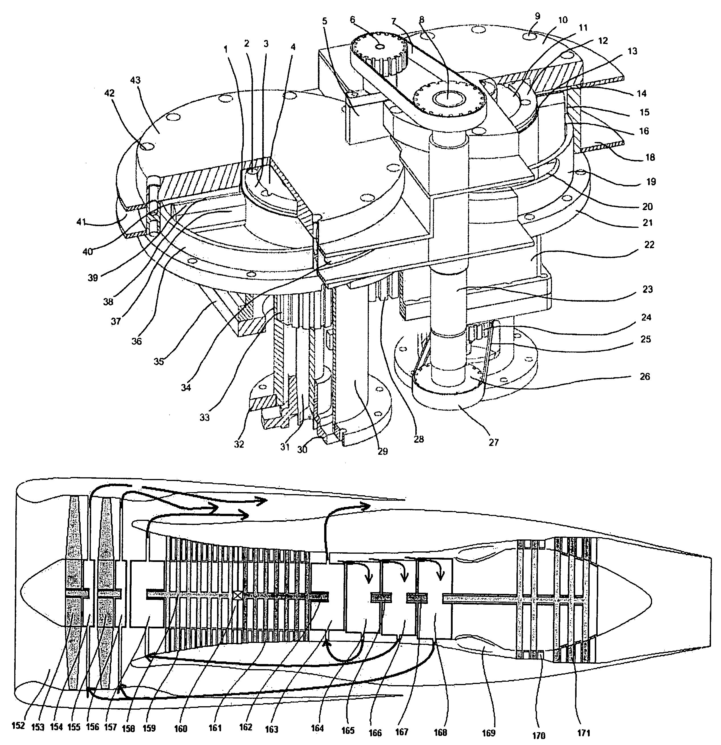
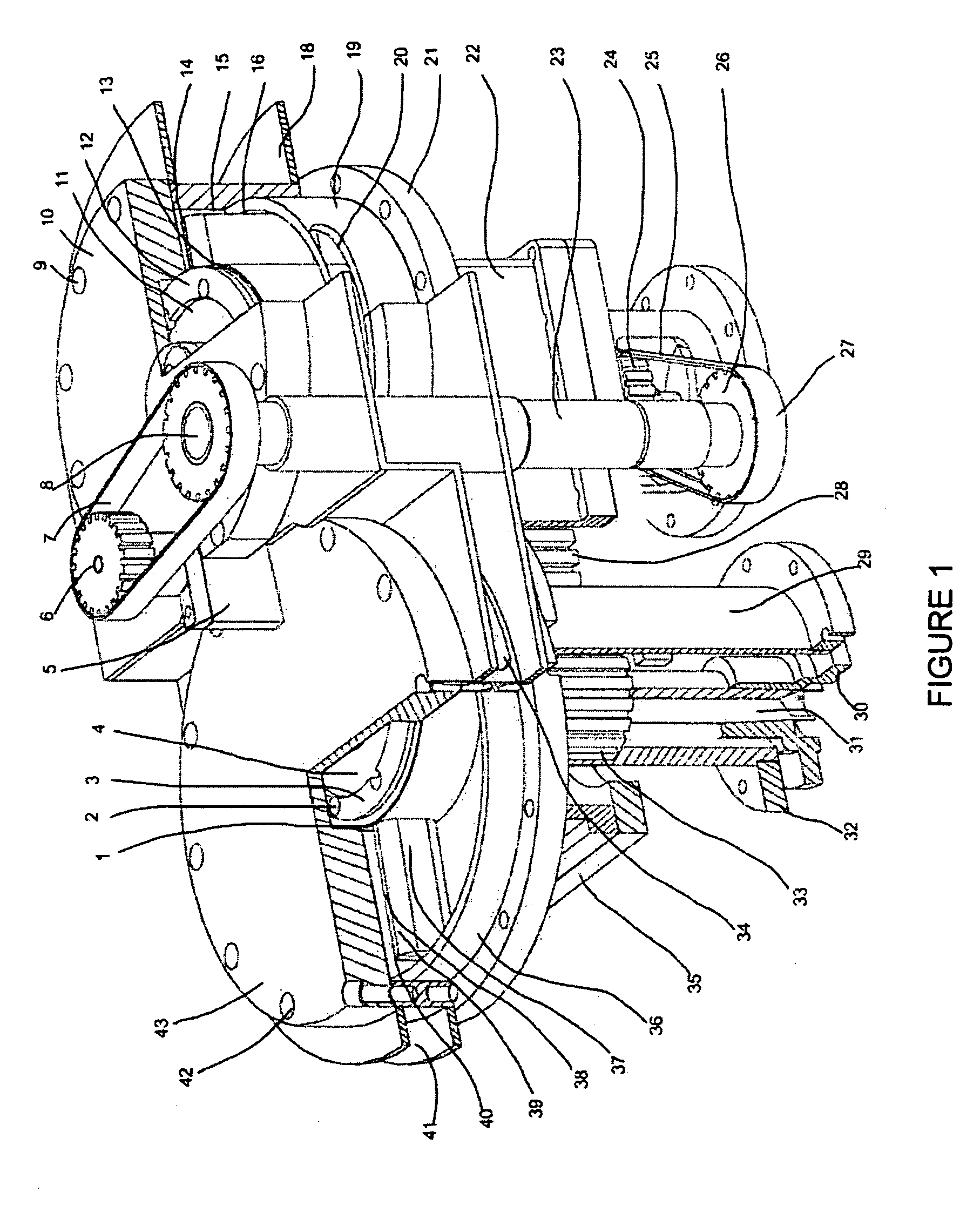
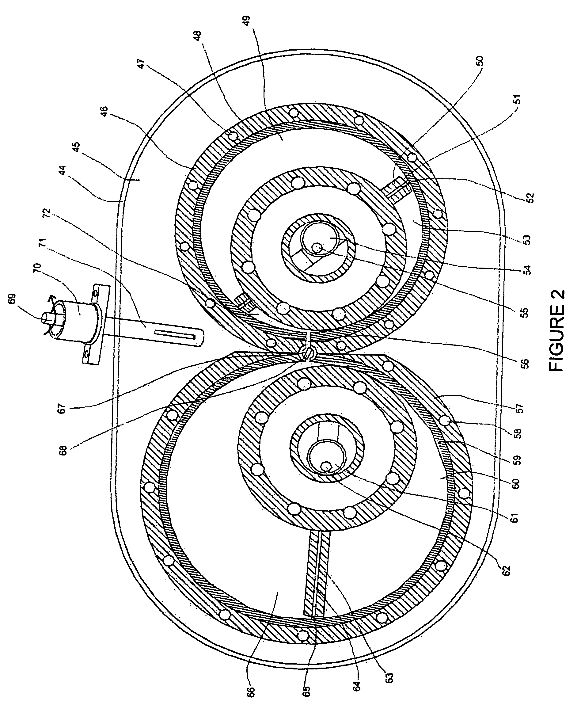
[0023]FIG. 1 and FIG. 2 depict a preferred embodiment of the internal combustion rotary engine where combustion occurs within the turbine chamber (66). FIG. 3 depicts a different preferred embodiment of an external combustion (74, 92) rotary engine where combustion starts in a chamber (72) prior to entry within the turbine expansion chamber (103). The rotary combustion engine casing (21, 35,44) comprises at least one rotary compressor unit wherein, said unit has inner (19,48) and outer (46) housings. The engine casing also comprises at least one rotary turbine unit wherein, said unit has inner (59) and outer (57) housings. Said housings are surrounded by a liquid cooled jacket (18,41,45). For example, water may be used as coolant. The housings have each, a circularly cylindrical (3, 13) rotor (12,128), rotatably and eccentrically mounted. The said rotary engine bre...


PUM


Abstract

A heat engine having a rotary vane compressor and a rotary vane turbine operates in a highly efficient thermodynamic cycle which includes a power expansion phase up to ambient pressure and a limited temperature constant volume combustion followed by a constant pressure combustion and / or a constant temperature combustion. A compound propulsion engine utilizing the thermodynamic cycle has a primary stage having an axial compressor and a rotary vane turbine, and a secondary stage having an axial turbine and a rotary vane compressor, the two stages being aero-thermodynamically coupled to each other without provision of an interconnecting drive shaft.

Description

CROSS REFERENCE TO RELATED APPLICATIONS[0001]This application is a U.S. national stage application of copending International Application No. PCT / TR03 / 00071, filed Sep. 9, 2003, claiming priority dates of Sep. 9, 2002 and Sep. 8, 2003, and published in the English language.FIELD OF THE INVENTION[0002]This invention relates to energy systems and more particularly to componentry and thermodynamic cycle for enabling shaft work, propulsion drive, electric power source, jet propulsion and thermodynamic systems such as ventilation, cooling, heat, pressure or vacuum generating systems.BACKGROUND OF THE INVENTION[0003]Since the start of the industrial revolution, the reciprocating piston engine based on the Otto and Diesel cycles and, the gas turbine engine based on the Brayton cycle, have largely dominated the market. Despite this fact, for many years, patents on rotary combustion engines have claimed that rotary engines possess many advantages over reciprocating engines such as having hig...

Claims


Application Information

Patent Timeline
Patent Type & Authority Patents(United States)
IPC IPC(8): F02B53/04F01C1/00F01C1/344F02B53/00F02K3/02F04C18/00F04C2/00F01C11/00F01C13/00F01C21/08F01C21/10F02C3/055
CPCB64C27/12F01C1/3442F01C11/004F01C11/008F01C13/00F01C21/0836F01C21/106F02C3/055F04C2250/301Y02E20/16F05D2220/32
Inventor AKMANDOR, IBRAHIM SINANERSOZ, NAZMI
Owner AKMANDOR IBRAHIM SINAN
Why Eureka
Try Eureka