
System and method for managing energy generation equipment

Inactive Publication Date: 2007-12-25
DTE ENERGY TECH
View PDF1 Cites 175 Cited by
  • Summary
  • Abstract
  • Description
  • Claims
  • Application Information

AI Technical Summary

Benefits of technology

[0012]In this way, the present invention balances remote dispatch commands against actual load conditions that are infrequently available at the source of the commands, the remote central controller in one embodiment. Equipment and software are provided for this purpose to practically use the suggestions from the remote location. In one embodiment, the present invention can make initial and locally influenced determinations entirely on site, such as by using the site controller. The present invention works with multiple types of generation equipment and control protocols, and considers economics, reserve margin, load following needs, redundancy requirements, actual electric and thermal load conditions and numerous other parameters to establish a comprehensive and thorough solution. Further, the present invention can receive operating instructions through the Internet and can make adjustments or complete changes to the received instructions to ensure that electric and thermal loads are served reliably.
[0014]The present invention further empowers facilities to measure productivity and improve predictability, benchmark energy facilities across the entire enterprise, maximize leverage with energy suppliers by negotiating and procuring lower rates, and allocate costs across multiple production lines, departments or processes. The present invention can also help facilities determine marginal energy cost of production for various products and configurations, determine the energy cost-effectiveness of different production strategies, and automatically determine when to rely on local generation to minimize costs.

Problems solved by technology

Determining when to operate each DGE within a distributed generation environment and at what power level can be a rather complex decision, affected by the cost of fuel, the cost of the electric power or heat that is deferred, and, in some cases, the impact of the emissions both from the DGE device and from the central generator, for example.
Such methods suffer from several disadvantages, including the inability to adapt the forecasting model to changing operational conditions in real time, especially on a site-specific basis.

Method used


Image

  • System and method for managing energy generation equipment
  • System and method for managing energy generation equipment
  • System and method for managing energy generation equipment

Examples


example operation

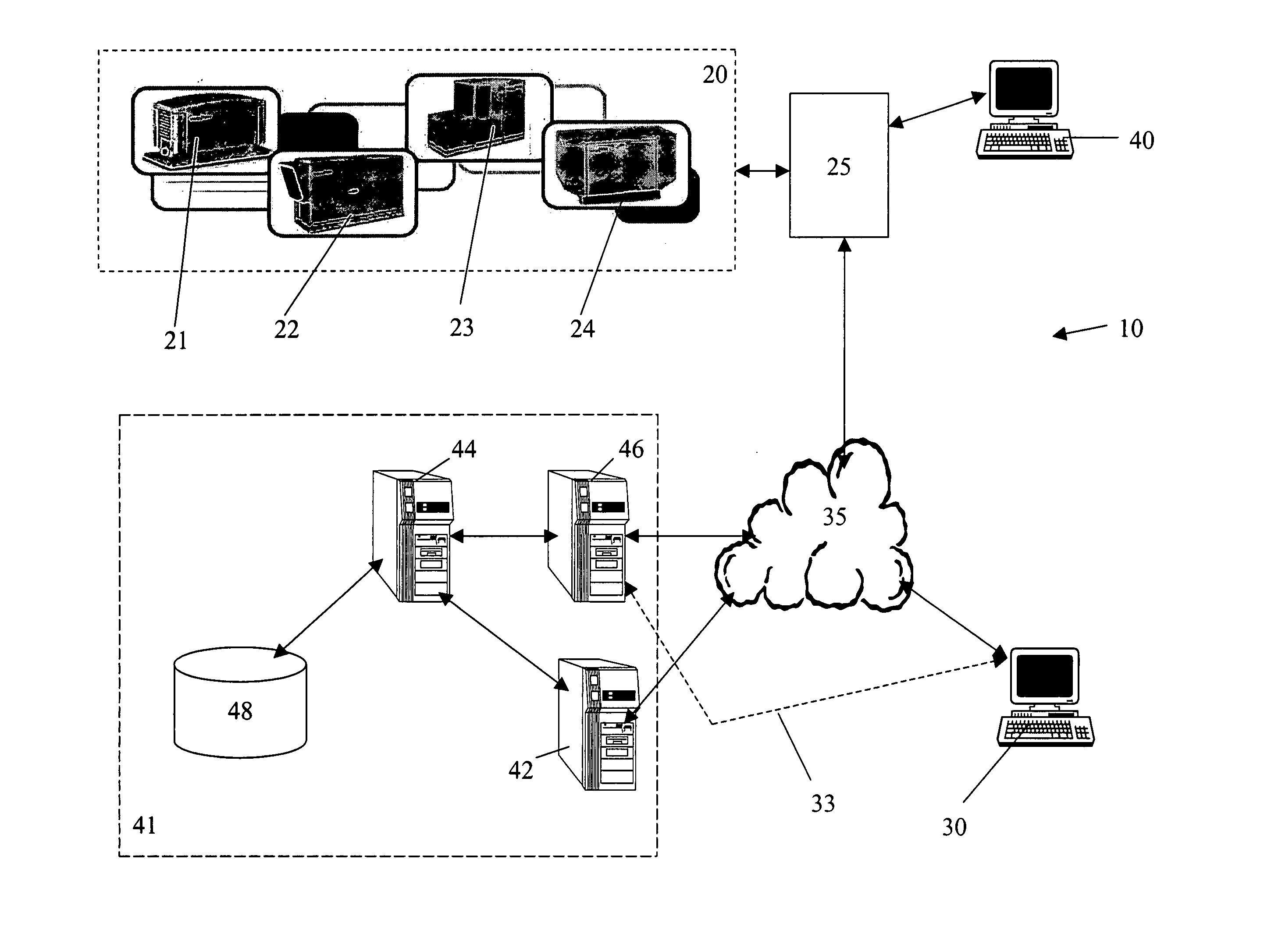
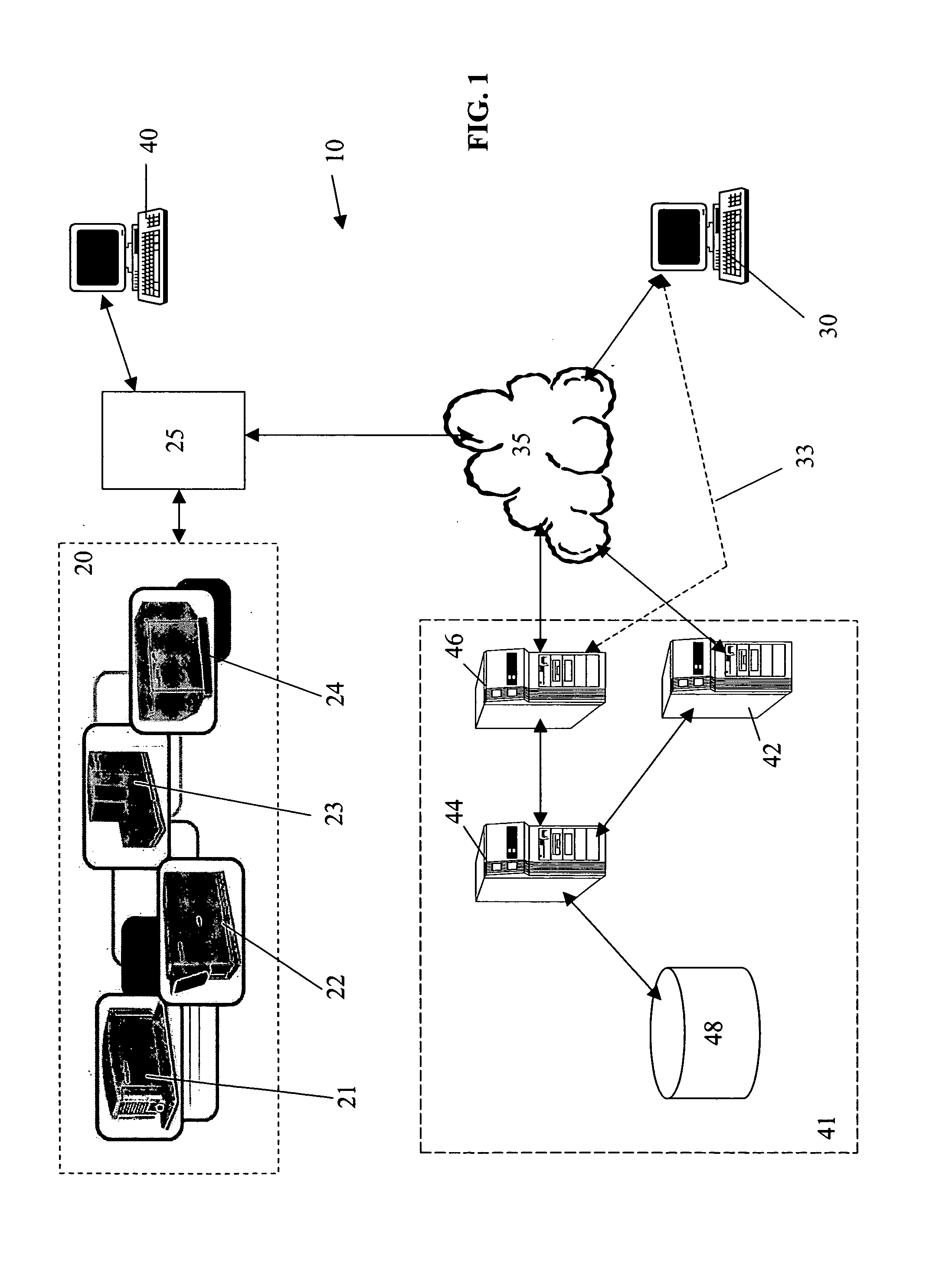
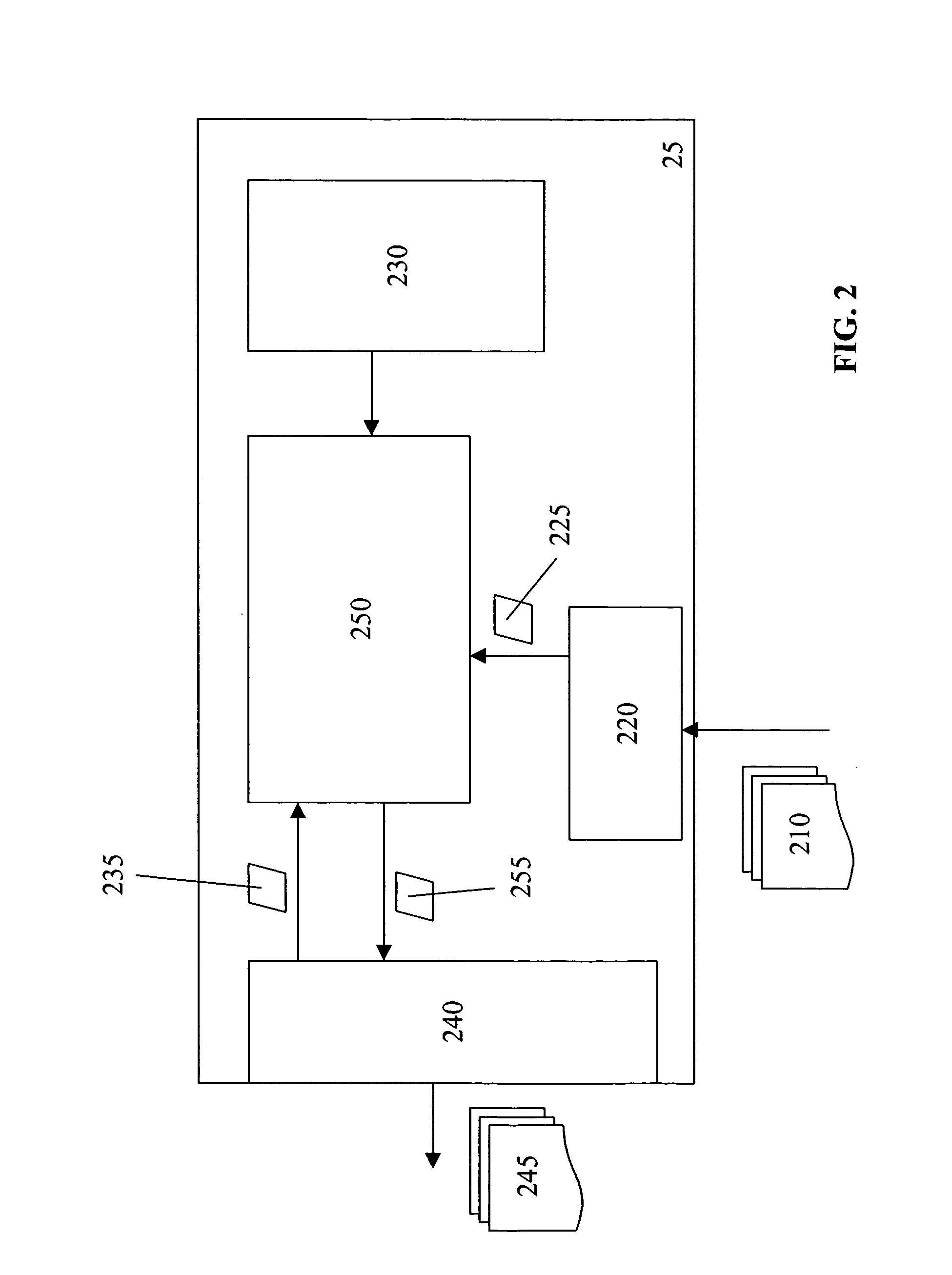
[0268]In a specific embodiment of the present invention, the economics of running DGE units is based on the load served, fuel costs, part load efficiencies, competing electric service prices, maintenance costs, unit availability, and meeting reserved margin requirements. The preliminary algorithms use forecasted data to determine the optimal economic operating point are run on servers 42, 44, 46 at the System Operation Center (SOC) 41. The local controls, including the site controller component 25, adjust the suggested commands from the SOC based on actual load conditions using site controller algorithm component 250.

Data Generated by SOC

[0269]In this embodiment, the SOC algorithms are based on whether the site being controlled is isolated or connected from the traditional grid. It will be appreciated that stand-alone operation is the operation of a single unit powering a dedicated power system with or without grid standby. In stand-alone operation, the unit never operates parallel ...


PUM


Abstract

A system and method for controlling distributed generation equipment based on remotely derived dispatch schemes improves economics and reliability of operation. The system can adapt to variable changing conditions in real-time to provide adaptable, real-time, site-specific load forecasting. The present invention can include one or more local site controller component(s) for receiving dispatch instructions and comparing the instructions to local information to further optimize operating instructions.

Description

CROSS REFERENCE TO RELATED APPLICATIONS[0001]This application claims the benefit of U.S. application No. 60 / 502,092, filed Sep. 11, 2003, entitled “System and Method for the Cost Effective and Reliable Operation of Electrical Generation Equipment”.FIELD OF THE INVENTION[0002]The present invention relates to distributed generation, and more particularly to a system and method for managing distributed generation equipment.BACKGROUND ART[0003]Commercial, residential and industrial facilities are becoming more versatile in managing their energy needs. Traditionally, nearly all energy consumers purchased power from a regulated utility, with few maintaining on-site generation for emergency backup. Now, some facilities are using on-site generation as primary power and other facilities are even selling locally-generated power back to the grid. Part of the reason for the change can be attributed to deregulation of the energy industry and the now widespread availability of distributed generat...

Claims


Application Information

Patent Timeline
IPC IPC(8): G05D11/00
CPCG06Q50/06Y04S10/54Y04S10/545Y02E40/76Y02E40/70Y04S10/50
Inventor O'DONNELL, JOHN
Owner DTE ENERGY TECH
Learn More