Seat structure for supporting an assembly from underneath
- Summary
- Abstract
- Description
- Claims
- Application Information
AI Technical Summary
Benefits of technology
Problems solved by technology
Method used
Image
Examples
Embodiment Construction
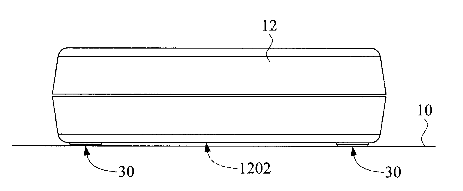
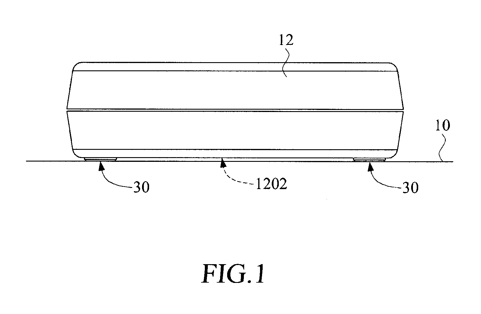
[0018]FIG. 1 is a perspective view of a seat structure 30 of the present invention for supporting an electronic assembly or device 12 from underneath. The seat structure 30 of the present invention is disposed below a base portion 1202 of the assembly 12 in order to absorb the vibration caused during operation of the assembly 12.
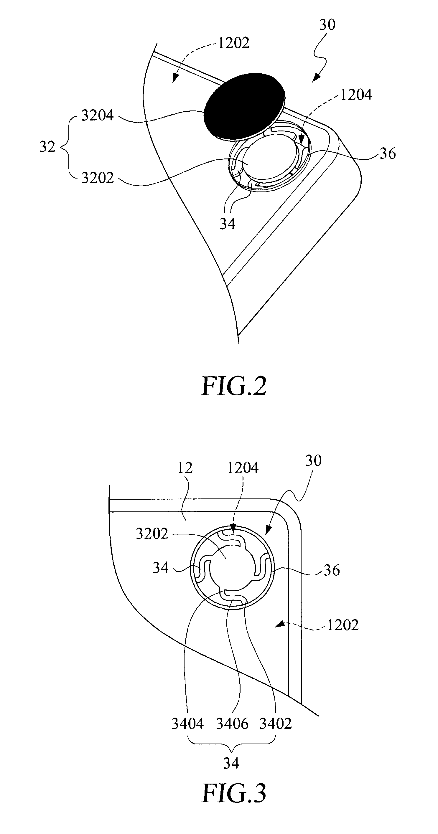
[0019]Referring to FIGS. 2 and 3, wherein FIG. 2 is an exploded view of the seat structure of the present invention, in which, the assembly 12 is turned upside down to illustrate attachment of the present seat structure 30 thereto. FIG. 3 is an enlarged view of a carrier disc and a bottom seat of the seat structure of the present invention. The base portion 1202 of the assembly 12 is formed with an opening 1204. In case the assembly 12 has four bottom corners, there should be four openings 1204 in the base portion 1202. Each seat structure 30 of the present invention includes a bottom seat 32 and a plurality of flexible connecting elements 34.
[0020]The botto...
PUM
 Abstract
Description
Claims
Application Information
 - R&D
- Intellectual Property
- Life Sciences
- Materials
- Tech Scout
- Unparalleled Data Quality
- Higher Quality Content
- 60% Fewer Hallucinations
Browse by: Latest US Patents, China's latest patents, Technical Efficacy Thesaurus, Application Domain, Technology Topic, Popular Technical Reports.
© 2025 PatSnap. All rights reserved.Legal|Privacy policy|Modern Slavery Act Transparency Statement|Sitemap|About US| Contact US: help@patsnap.com


