
Roof cover plate for the cabin of a car

a technology for car cabins and roof covers, which is applied in the direction of roofs, transportation items, transportation and packaging, etc., can solve the problems of poor stability, high fuel consumption, and insufficient back seat space for adults, and achieves poor stability, high fuel consumption, and low traveling speed

Inactive Publication Date: 2007-12-18
WANG ZHENGZHONG
View PDF19 Cites 1 Cited by
  • Summary
  • Abstract
  • Description
  • Claims
  • Application Information

AI Technical Summary

Benefits of technology

"The invention provides a roof cover plate for passenger cars and sport cars that can provide fast traveling speed, excellent stability, less fuel consumption, simple structure, low manufacturing cost, and enough space in the back seat for adult people. The roof cover plate can be adjusted to a certain level to make the passenger in the back seat feel comfortable, without being limited by the height of door frames on both sides of cabin. The car can function as a passenger car and a sport car by raising and lowering the roof cover plate. The invention is applicable to various kinds of passenger cars and sport cars."

Problems solved by technology

In comparison with a sport car, the car with a fixed cabin roof cover plate, which has substantially the same height in the front and rear, provides lower traveling speed, poor stability and high fuel consumption.
The sport car with a fixed cabin roof plate, which has large backward slope and has a much lower height in the rear side than in the front side, can not provide enough space in the back seat for adult people, and only children and pets can be fitted into the back seat.

Method used


Image

  • Roof cover plate for the cabin of a car
  • Roof cover plate for the cabin of a car
  • Roof cover plate for the cabin of a car

Examples


embodiment 1

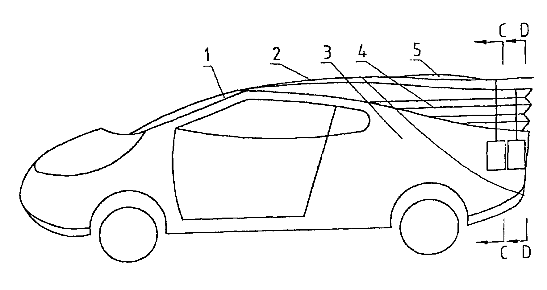
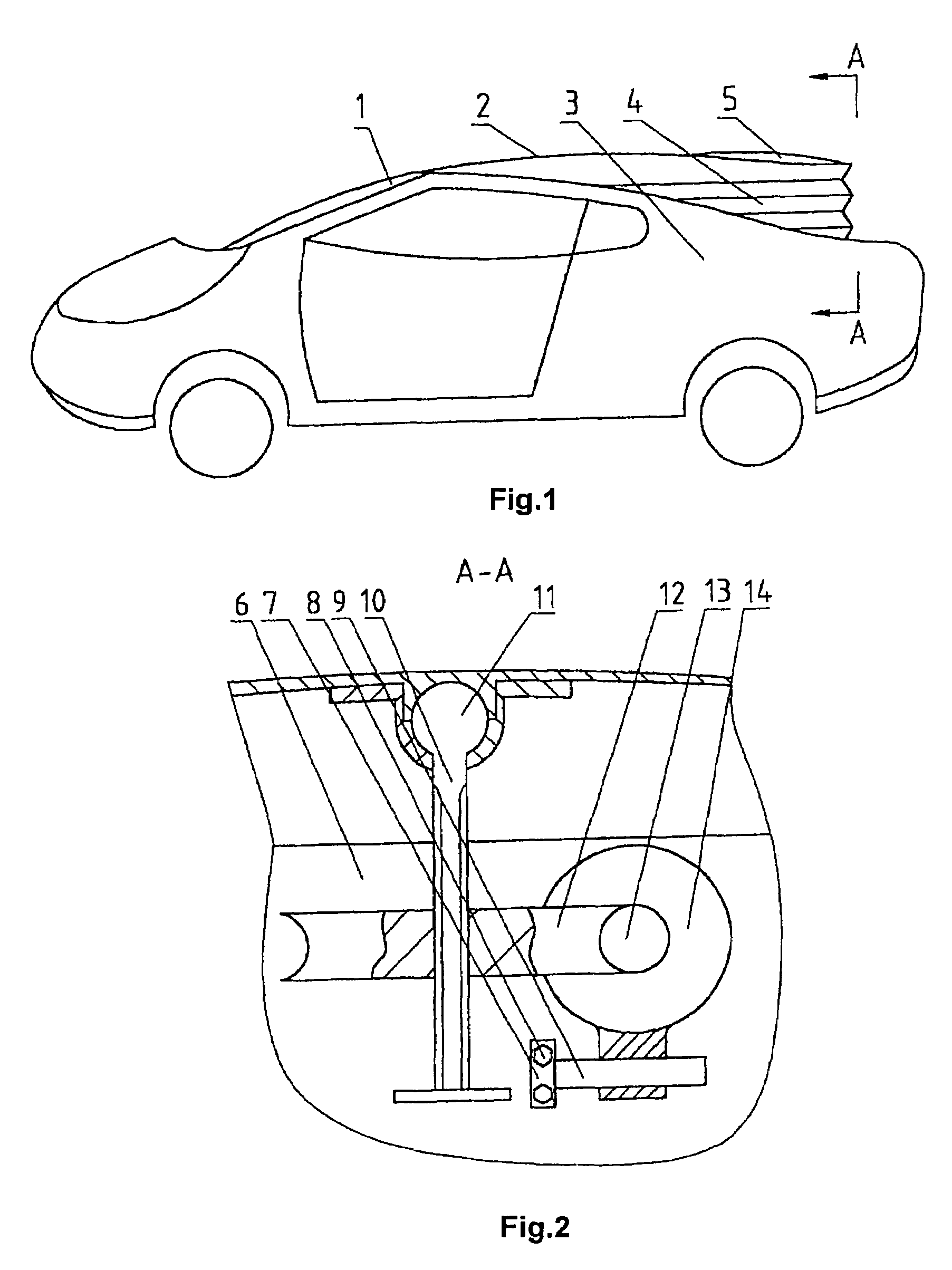
[0010]FIGS. 1 and 2 show the roof cover plate for the cabin of a car. A front windshield 1 is provided at the front side of the cabin, and a rear structure 6 is provided at the rear side of cabin. The car door frames 3 are provided at the left and right sides of the cabin. The car door frames 3 are connected with the front windshield 1 at the front side, and are connected with the rear structure 6 at the rear side, thus forming the surrounding border of the cabin. The front end of a cover panel 2 is hinged to the upper portion of the surrounding border which is located above the front windshield, as shown in FIG. 1. The connection of the cover panel 2 at a location above the front windshield can be achieved by means of a hinge, rubber or plastic etc. which functions as a hinge joint, so that the cover panel 2 can be raised and lowered. The cover panel 2 is provided with a rear windshield 5 at its rear portion, and forms an integral roof cover plate of the cabin together with the rea...

embodiment 2

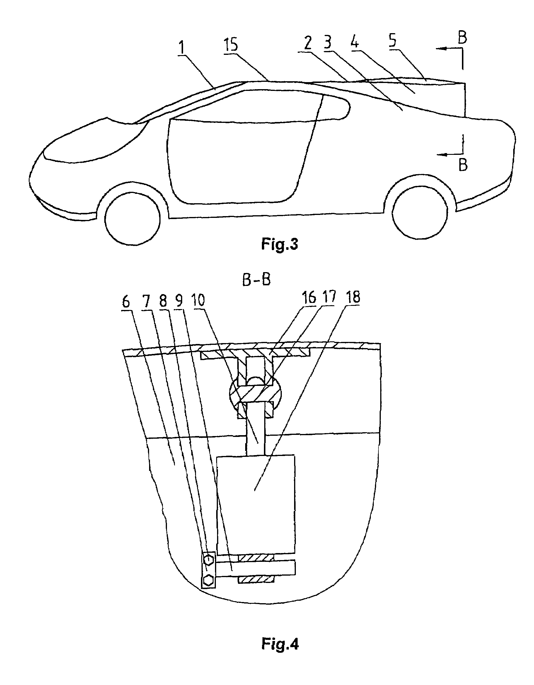
[0011]FIGS. 3 and 4 show the roof cover plate for the cabin of a car. A front windshield 1 is provided at the front side of the cabin, and a rear structure 6 is provided at the rear side of the cabin. The car door frames 3 are provided at the left and right sides of the cabin. The car door frames 3 are connected with the front windshield 1 at the front side, and are connected with the rear structure 6 at the rear side, thus forming the surrounding border of the cabin. The front end of a cover panel 2 is hinged to the upper portion of the surrounding border of the cabin. As shown in FIG. 3, a fixed cover panel 15 is fixedly connected to the upper end of the front windshield 1 and the upper end of the front portion of the car door frames 3, the front end of the cover panel 2 is hinged to the rear end of the fixed cover panel 15, and the front end of the cover panel 2 can be hinged to the rear end of the fixed cover panel 15 by means of a hinge, rubber or plastic etc. which functions a...

embodiment 3

[0012]FIGS. 5, 6 and 7 show the roof cover plate for the cabin of a car. A front windshield 1 is provided at the front side of the cabin, and a rear surrounding border is provided at the rear side of cabin. The car door frames 3 are provided at the left and right sides of the cabin. The car door frames 3 are connected with the front windshield 1 at the front side, and are connected with the rear surrounding border at the rear side, thus forming the surrounding border of the cabin. The front end of a cover panel 2 is hinged to the upper portion of the surrounding border which is located above the front windshield 1, as shown in FIG. 5. The connection of the cover panel 2 at a location above the front windshield can be achieved by means of a hinge, rubber or plastic etc. which functions as a hinge joint, so that the cover panel 2 can be raised and lowered. The cover panel 2 is provided with a rear windshield 5 at its rear portion, and forms an integral roof cover plate of the cabin to...


PUM


Abstract

The invention provides a cab roof of a vehicle with a movable panel. The cab is provided with a front windscreen, a rear deck or rear walls, and door frames at both sides. The door frames are connected with the front windscreen at the front side, with the rear decks or rear walls at the rear side, forming the enclosing sidewalls of the cab. The connecting cover is hinged with the enclosing sidewalls at the front end, and is provided with rear windscreen at the rear end. The entire cab roof is consisted of the connecting cover and the rear windscreen. A telescopic bellow is at the bottom of the cab roof, which connects the enclosing sidewalls at the lower portion. A raising and lowering device is at the bottom of the rear side of the cab roof. The vehicle can be used as a car where passengers can be seated in the rear seats, and as well as a sports car where the cab roof drops on the enclosing sidewalls by pressing the telescopic bellow. The vehicle, which can play the two roles, is applied to various kinds of cars and sports cars.

Description

CROSS-REFERENCE TO RELATED APPLICATIONS[0001]This application is a U.S. national application under 37 C.F.R. § 371(b) of international application serial no. PCT / CN2004 / 001304 filed Nov. 15, 2004, which claims priority to Chinese application serial no. 200310116713.6 filed Nov. 18, 2003.FIELD OF THE INVENTION[0002]The present invention relates to a movable roof panel of a car and, more particularly, to a roof cover plate for the cabin of a car.BACKGROUND OF THE INVENTION[0003]As we all know, in a full-size passenger car and a sport car, a front windshield and a rear structure are provided at the front side and the rear side of a cabin respectively. The rear structure, such as a separator wall or plate, separates the cabin from the trunk of the car. A rear windshield is provided above the rear side of the rear structure. Door frames are provided at both sides of the cabin. A surrounding border of the cabin is formed by connecting the car door frames with the front windshield at the f...

Claims


Application Information

Patent Timeline
Patent Type & Authority Patents(United States)
IPC IPC(8): B60J7/08B60J7/16
CPCB60J7/1657B60J7/16B60J7/00B60J7/08
Inventor WANG, ZHENGZHONG
Owner WANG ZHENGZHONG
Learn More