Information reception device, information transmission system, and information reception method
a technology of information transmission system and information reception device, which is applied in the field of information reception device, information transmission system and information reception method, can solve the problems of wasteful image processing, inaccurate extraction of information from optical tag unit, and inconvenient so as to accelerate information decoding processing and facilitate the effect of position adjustment of optical modulation region
- Summary
- Abstract
- Description
- Claims
- Application Information
AI Technical Summary
Benefits of technology
Problems solved by technology
Method used
Image
Examples
first embodiment
A. FIRST EMBODIMENT
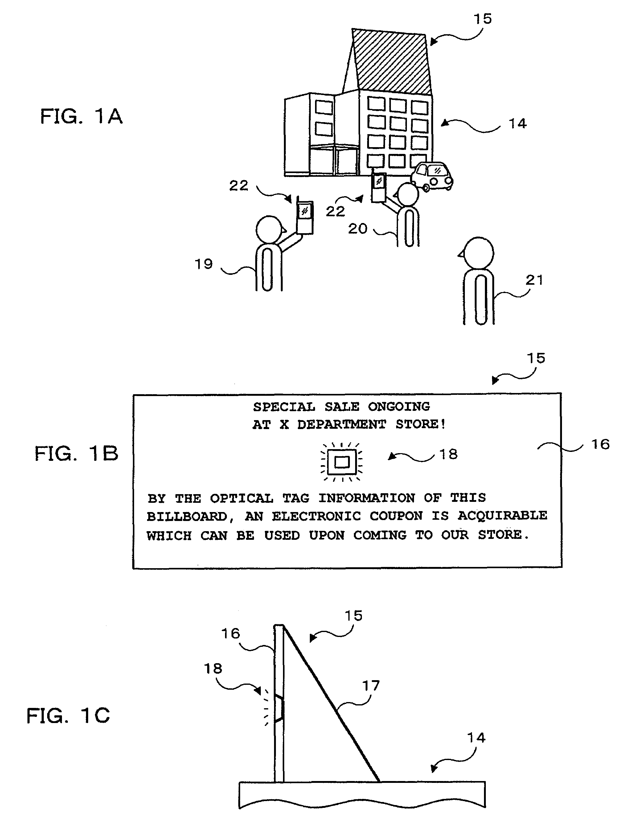
[0072]FIGS. 1A˜1C are usage status diagrams of an information transmission system in the first embodiment. First, FIG. 1A illustrates an advertisement display board 15 installed on the roof of a structure 14, such as a building. In FIG. 1B, this advertisement display board 15 is shown in a front elevation view and FIG. 1C shows a side view. The billboard 16 depicts a large optional description character string (In FIG. 1B, “SPECIAL SALE ONGOING AT X DEPARTMENT STORE!”, “BY THE OPTICAL TAG INFORMATION OF THIS BILLBOARD, AN ELECTRONIC COUPON IS AQUIRABLE WHICH CAN BE USED UPON COMING TO THE STORE.”). As shown in FIG. 1C, a back stationary reinforcement 17 supports the billboard 16 from behind. From a distance, the descriptive character string can be visually identified.
[0073]An optical tag unit 18 is mounted in an optional position of the billboard 16 (substantially the center portion in the example illustration). The optical tag unit 18 is a point light source whic...
second embodiment
B. SECOND EMBODIMENT
[0162]Apart from the above, although in the above-mentioned first embodiment the photodetector 61 is used as a light reception means for light reception of the luminescent spot of the optical tag unit 18, the present invention is not restricted to this. What is necessary is to have an angle of view corresponding to the size of the information offering object (the optical tag unit 18). For example, this may be an image sensor, such as a CCD, CMOS, etc., or a plurality of photodetectors arranged on a plane surface.
[0163]Hereinafter, the second embodiment using an image sensor, such as a CCD, CMOS, etc, will be explained.
[0164]FIG. 25 is an internal block configuration diagram of the camera cell-phone 220 in the second embodiment. As shown in FIG. 25, the camera cell-phone 220 has the feature point of comprising an image sensor for communication 610 in place of the image sensor 57 of the photodetector 61 in the above-described first embodiment (hereinafter, also den...
PUM
 Abstract
Description
Claims
Application Information
 - R&D
- Intellectual Property
- Life Sciences
- Materials
- Tech Scout
- Unparalleled Data Quality
- Higher Quality Content
- 60% Fewer Hallucinations
Browse by: Latest US Patents, China's latest patents, Technical Efficacy Thesaurus, Application Domain, Technology Topic, Popular Technical Reports.
© 2025 PatSnap. All rights reserved.Legal|Privacy policy|Modern Slavery Act Transparency Statement|Sitemap|About US| Contact US: help@patsnap.com


