High-stability optical microscope

a high-stability, optical microscope technology, applied in the direction of telescopes, mountings, instruments, etc., can solve the problems of unstable optical microscopes, insufficient stability of optical microscopes, and fluctuation of optical axis in so as to achieve stable optical imaging and photometric systems, the effect of free from asymmetry

Inactive Publication Date: 2007-12-11
JAPAN SCI & TECH CORP
View PDF10 Cites 7 Cited by
  • Summary
  • Abstract
  • Description
  • Claims
  • Application Information

AI Technical Summary

Benefits of technology

[0012]Another technical means adopted by this invention is a structure of a highly stable optical microscope in which the support structure for the optical imaging system and photometric system are either a square truncated pyramid or circular truncated cone, to prevent changes in inclination caused by temperature fluctuations, vibration or other factors.
[0013]Another technical means adopted by this invention is a structure of a highly stable optical microscope in which, in an infinity corrected optical microscope, a half mirror (including dichroic mirror) and an imaging lens are combined and mounted at, the inlet of the optical lighting system (incident-light fluorescence, total internal reflection fluorescence, transmitted light fluorescence, incident polarized light, transmitted polarized light, bright field incidence, optical tweezers and etc.) and also the optical monitor system, respectively, to make the optical imaging and photometric systems stable and free from the asymmetry of shape and mass and instability caused by temperature dependency of the metal support structures by utilizing the principle of a telescope.

Problems solved by technology

The important components of an optical photometric system and optical imaging system, corresponding to the trunk of the tree, are unstable because the main stand is set on one end of the base and the illumination system.
The support fixtures for the illumination system are integrated with the optical imaging and photometric systems, with the result that instability caused by asymmetry in the shape and mass of the support fixtures for the illumination and monitor systems and shrinkage / elongation of those support fixtures due to temperature dependency bring about the fluctuation of the optical axis in the optical imaging and photometric systems.
Currently available optical microscopes are not stable enough and drift occurs during observation, recording and measurement performed for extended times. The observation results are always subject to errors.

Method used


Image

  • High-stability optical microscope
  • High-stability optical microscope
  • High-stability optical microscope

Examples


Embodiment Construction

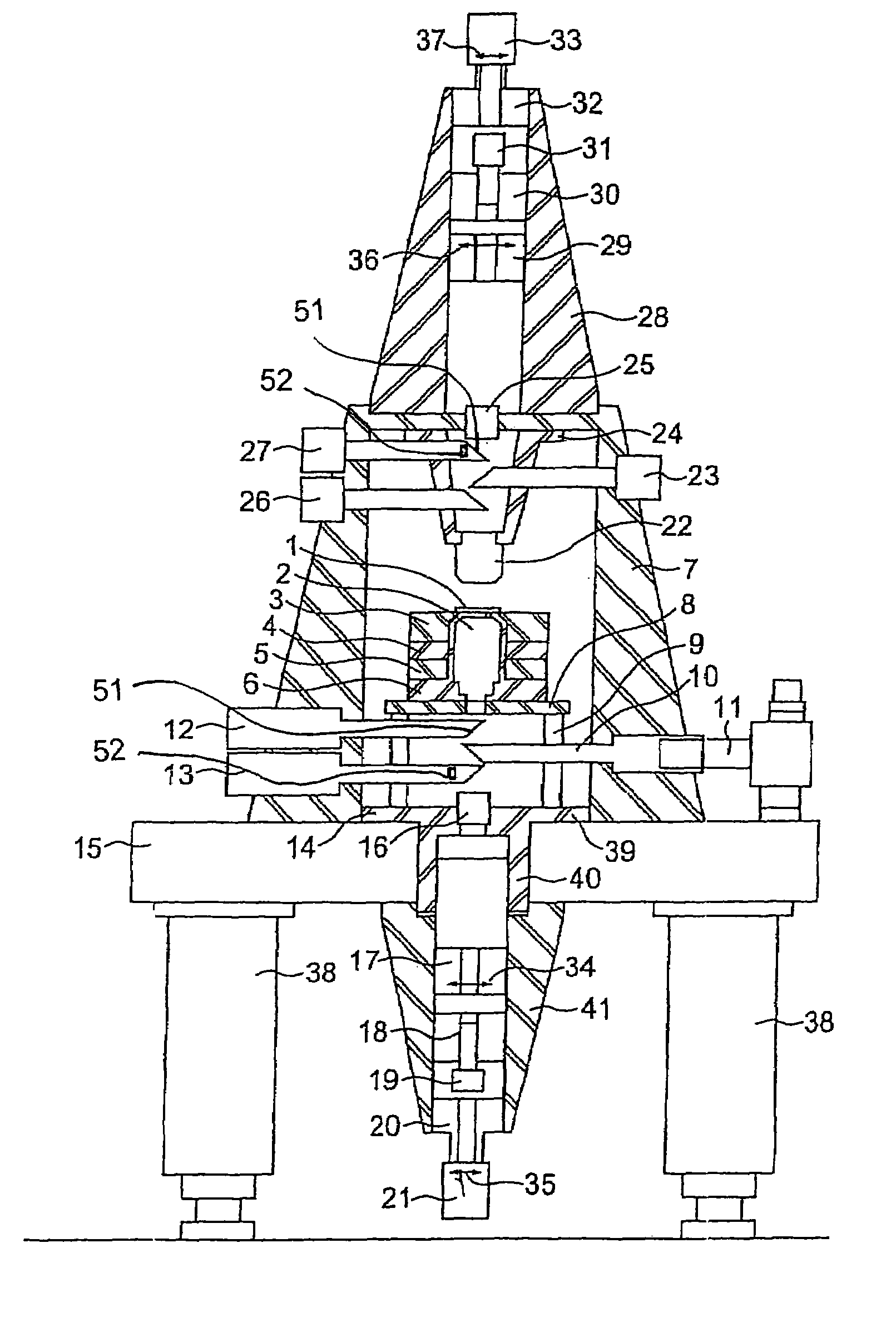
[0020]The highly stable optical microscope of this invention is described below referring to FIG. 3.

[0021]The infinity corrected optical microscope comprises an optical imaging system (consisting of photometric iris 17, relay lens support fixture 18, relay lens 19, television camera support fixture 20, and television camera 21), an optical photometric system (consisting of straight tube 28, photometric iris 29, relay lens fixture 30, relay lens 31, photometric system support fixture 32, and photometric system 33), an illumination system (consisting of incident-light fluorescence 12, total-internal- reflection-fluorescence, transmitted light fluorescence, incident polarized light, transmitted polarized light, bright field incidence, optical tweezers 10 and 11, and etc.), and the infinity corrected objective lens 2 and imaging lens 16 built into the optical lighting system. A hollow conical support base 7 is fixed on the vibration isolating table 15, which is supported by support legs...


PUM


Abstract

This invention provides a highly stable optical microscope that prevents drift and makes it possible to record images or take measurements for several hours with accuracy in the order of nanometers. The highly stable optical microscope of this invention includes the support structure (41) that accommodates and supports components including the optical imaging system, straight tube (28) that accommodates and supports components including the optical photometric system, and support structure (7) that accommodates and supports components including the illumination system. These support structures have a hollow pyramid or conical shape with a low center of gravity. The highly stable optical microscope of this invention features the objective lenses, imaging lenses, optical imaging and photometric systems that are mounted, forming a straight line, on the supporting structures that are symmetrical about the optical axis in both shape and mass.

Description

TECHNICAL FIELD[0001]This invention relates to image recording and measuring for an extended time using optical equipment, optical measuring instruments or optical microscopes. When an optical microscope, in particular, is used to record images or measurements for an extended time, the microscope is displaced minutely such that the object point (object) is shifted or defocused (so-called drift). This invention provides a structure for a highly stable optical microscope that is suitable for stable image recording or measuring for several hours with an accuracy in the order of nanometers by preventing drift.BACKGROUND OF THE INVENTION[0002]Conventional optical microscopes may be compared to a willow tree. The sample positioning stage, illumination system, optical observation system and other components mounted on the main stand (corresponding to the trunk of the tree) lack balance and are asymmetrical about the optical axis in both mass and shape. Such an unstable structure is shown i...

Claims


Application Information

Patent Timeline
Patent Type & Authority Patents(United States)
IPC IPC(8): G02B21/00G02B21/24G02B21/36
CPCG02B21/362G02B21/24
Inventor KINOSHITA, KAZUHIKOSHIO, MEGUMU
Owner JAPAN SCI & TECH CORP
Why Eureka
Try Eureka