System and method for adaptive duty cycle optimization
a technology of duty cycle optimization and system, applied in the field of data transmission, can solve the problems of affecting the efficiency of data transmission, the inability to optimize data transmission, and the loss of a portion of the information within the data signal stream at the receiver
- Summary
- Abstract
- Description
- Claims
- Application Information
AI Technical Summary
Benefits of technology
Problems solved by technology
Method used
Image
Examples
first embodiment
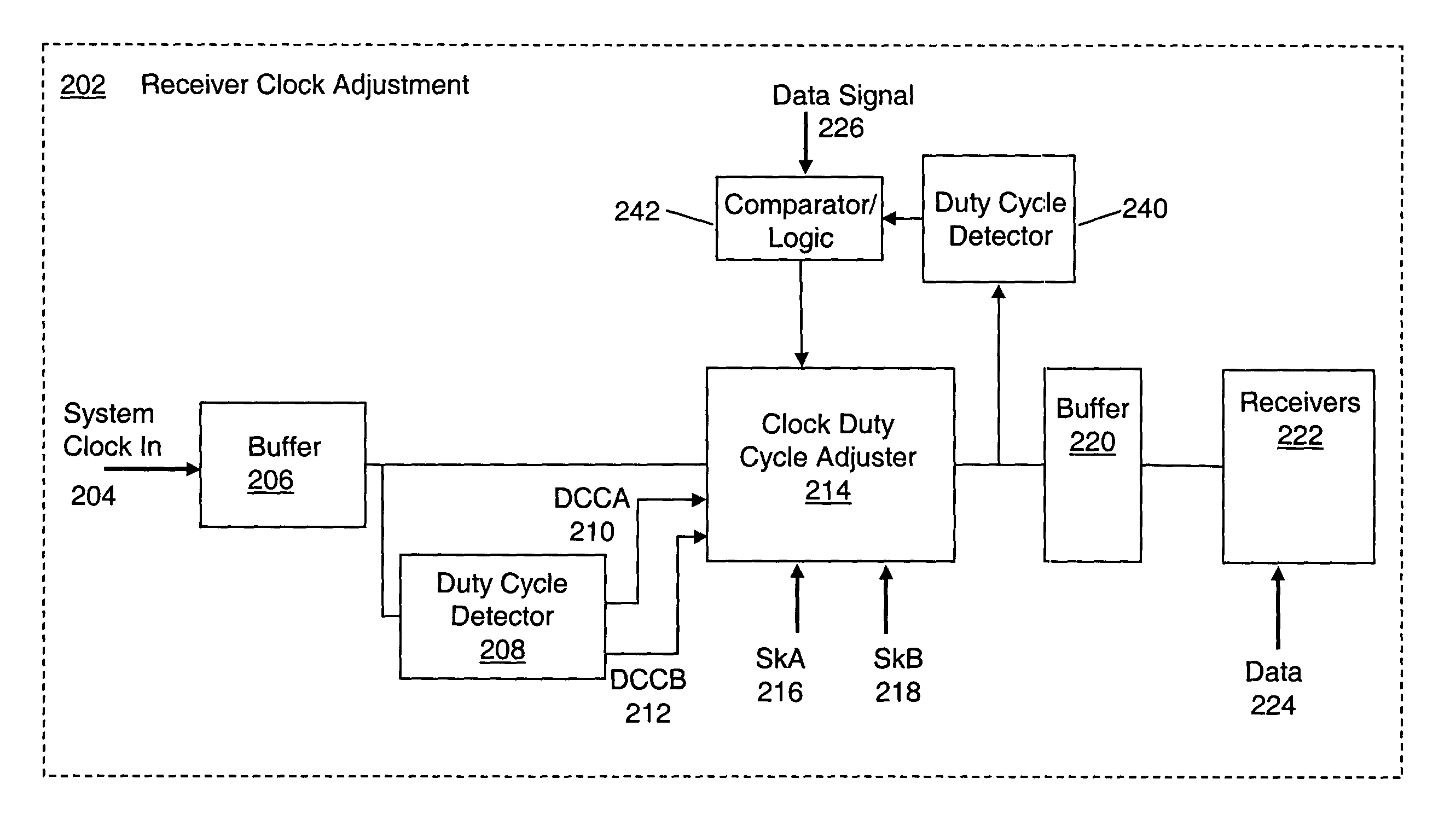
[0038]While the present invention may be implemented using any of a variety of duty cycle detectors, two embodiments of a duty cycle detector are described here. FIG. 2D depicts a duty cycle detector 250-A, suitable for detecting the duty cycle of a system clock signal or the duty cycle of a periodic data signal (see detectors 208, 240 in FIG. 2C). A data signal would be periodic during, for example, a calibration period. Alternately, the data signal may be a “bit balanced signal” having equal numbers of 1-bits and 0-bits during a calibration period. Detector 250-A includes a common mode detector 252, which may be implemented as a low pass filter. The common mode detector 252 outputs a signal 253 that equals or represents the average voltage level of the input signal 251 to the detector 252. The input signal may be either a clock signal or a data signal. The output signal 253 is compared with a reference voltage 256 (or other appropriate reference signal) by a comparator 254. The re...
second embodiment
[0039]a duty cycle detector 250-B is shown in FIG. 2E. This detector 250-B uses a digital sampling methodology instead of the analog methodology of the detector 250-A shown in FIG. 2D. The detector 250-B of FIG. 2E includes a digital signal sampler and averager 270 which samples an input signal 271 so as to develop an output signal 273 representative of the either common mode voltage or the duty cycle of the input signal 271. The signal sampler and averager 270 may be configured to sample the input signal, over a period of many clock cycles, so as to sample the input signal at an evenly distributed set of clock phases (e.g., at even increments of 2°). This may be done under the control of control logic 272, which may provide sampling timing signals to the signal sampler. The output signal 273 from the signal sampler and averager 270 is compared with a reference value 276 (which is a reference voltage value when the output signal 273 represents an input signal average voltage) by an ...
PUM
 Abstract
Description
Claims
Application Information
 - R&D
- Intellectual Property
- Life Sciences
- Materials
- Tech Scout
- Unparalleled Data Quality
- Higher Quality Content
- 60% Fewer Hallucinations
Browse by: Latest US Patents, China's latest patents, Technical Efficacy Thesaurus, Application Domain, Technology Topic, Popular Technical Reports.
© 2025 PatSnap. All rights reserved.Legal|Privacy policy|Modern Slavery Act Transparency Statement|Sitemap|About US| Contact US: help@patsnap.com


