
Method for producing monocrystalline structures

a monocrystalline and structure technology, applied in the direction of crystal growth process, machine/engine, gel state, etc., can solve the problems of insufficient crystal orientation, insufficient non-epitaxial growth, and insufficient mechanical properties, so as to prevent recrystallization and creep in the crystal structure, the effect of reducing internal stresses

Inactive Publication Date: 2007-12-11
SIEMENS AG +1
View PDF14 Cites 7 Cited by
  • Summary
  • Abstract
  • Description
  • Claims
  • Application Information

AI Technical Summary

Benefits of technology

The invention provides a method for building up monocrystalline layers on a substrate in a way that preserves the substrate's monocrystalline structure. This is achieved by using an epitaxial method that avoids the formation of globulitic structures and ensures the layers are built up in a monocrystalline manner. The method can be used to recondition damaged or worn monocrystalline workpieces by adding layers in a monocrystalline manner until the original size and form of the workpiece is achieved again. The method uses high energy beams, such as laser or electron beams, to melt the material and direct it onto the substrate. The resulting monocrystalline layers have advantages such as improved crystal structure and reduced stress in the substrate. The method can also be used to build up complex forms of monocrystalline layers, such as plates or layers with a specific crystal orientation.

Problems solved by technology

In these methods, the transition to globulitic (polycrystalline) solidification must be avoided, since this non-directional growth necessarily forms transverse and longitudinal grain boundaries, which nullify the good properties of the directionally solidified or monocrystalline component.
This results in overlapping or touching of individual weld beads (strips on which new material adjacently grows), which because of the geometrical conditions lead to non-epitaxial growth with insufficient crystal orientation.
As a consequence, mechanical properties are inadequate.

Method used


Image

  • Method for producing monocrystalline structures
  • Method for producing monocrystalline structures
  • Method for producing monocrystalline structures

Examples


Embodiment Construction

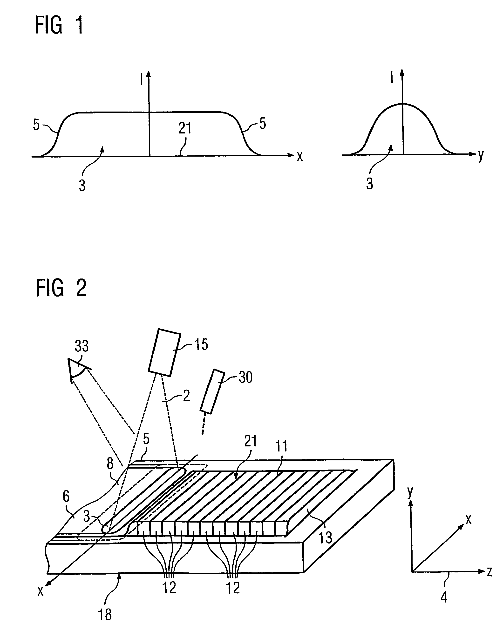
[0030]FIG. 1 shows an intensity distribution in cross sections of a focal spot which is used for the method according to the invention,

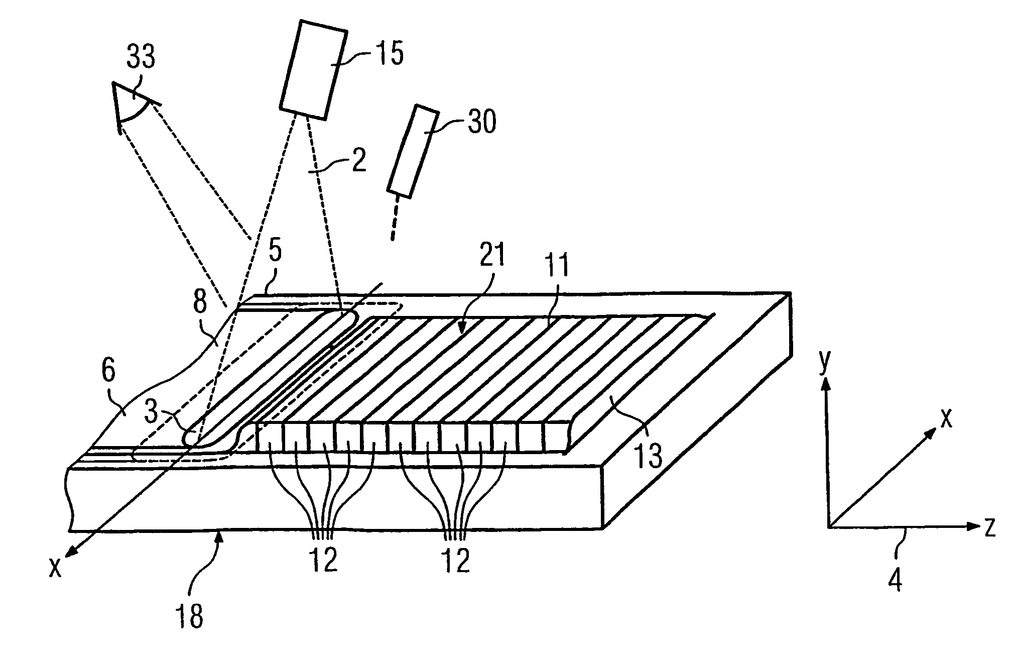
[0031]FIG. 2 a focal spot on a component for which the method according to the invention is used,

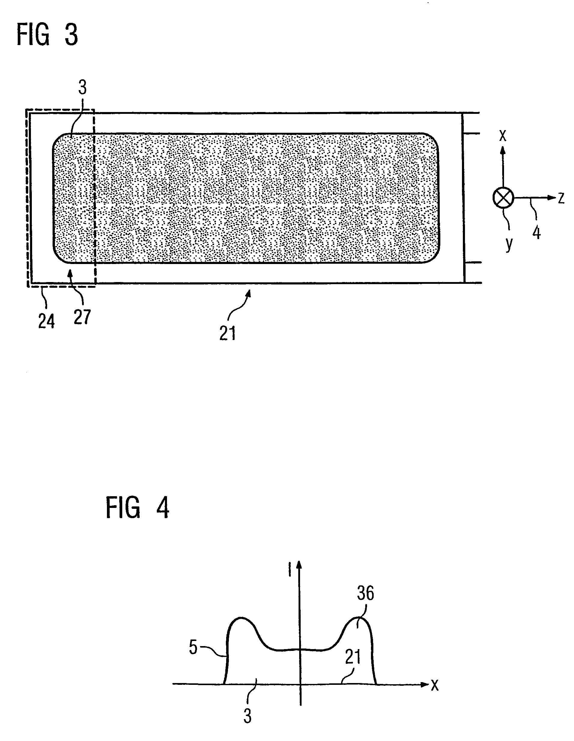
[0032]FIG. 3 a beam spot and the focal spot,

[0033]FIG. 4 an intensity distribution in a cross section of a focal spot which is used for the method according to the invention, and

[0034]FIG. 5 a method sequence according to the prior art.

[0035]FIG. 1 shows the intensity distribution of the beam 2 (FIG. 2) of an energy source in a focal spot 3 in a plane, the said spot not being circular but formed with different widths in the x and y directions.

[0036]The x direction is referred to hereafter as the width. The z direction corresponds to a direction of advancement 4 (FIG. 2). The plane (x-z plane) corresponds to the surface 21 to be treated of a component 6 (FIG. 2).

[0037]In the x direction, the beam 2 has, for example, a virtually rectangular profile of the i...


PUM

PropertyMeasurementUnit
temperatureaaaaaaaaaa

Abstract

In the case of the epitaxial growth according to the prior art, a number o strips often have to be produced in a plane in order to restore an area to be repaired. This leads to overlapping and misorientation of the crystalline structures. In the case of the method according to the invention, the strip is of such a width that no overlapping occurs, since the width is adapted to the contour of the area to be repaired.

Description

CROSS REFERENCE TO RELATED APPLICATIONS[0001]This application is a continuation of International Application No. PCT / DE03 / 00952, filed Mar. 21, 2003 and claims the benefit thereof. The International Application claims the benefits of German application No. 10216662.5, filed Apr. 15, 2002, and of German application No. 10243558.8 filed Sep. 19, 2002, all three of the applications are incorporated by reference herein in their entirety.FIELD OF INVENTION[0002]The invention relates to a method for producing directionally solidified and monocrystalline structures, in particular from superalloys, according to the precharacterizing clause of the independent claim 1.BACKGROUND OF INVENTION[0003]Metallic workpieces with a monocrystalline structure or structures are used as components of machines which are exposed to high mechanical, thermal and / or chemical loads during operation. For example, blades of gas turbines, in particular including those of rotors for aircraft engines, but also those...

Claims


Application Information

Patent Timeline
Patent Type & Authority Patents(United States)
IPC IPC(8): C30B13/00B23P9/00B22D27/04B23K15/00B23K26/00B23K26/06B23K26/073C30B11/00C30B13/22C30B13/24F01D5/28F02C7/00
CPCB23K15/0093B23K26/345B23K26/0736B23K26/0738C30B11/00C30B13/00C30B13/24B23K26/0732B23K26/3213B23K26/3206C30B29/52Y10S117/905Y10S117/904B23K26/32B23K26/342B23K2101/001B23K2103/02B23K2103/26B23K2103/50B22F10/28B22F10/25B22F12/44
Inventor BECK, THOMASBOSTANJOGLO, GEORGCOX, NIGEL-PHILIPWILKENHONER, ROLF
Owner SIEMENS AG
Learn More