
Network fault isolation

a fault isolation and network technology, applied in the field of network fault isolation, to achieve the effect of improving fault isolation knowledge, network uptime, reliability, performance, and response/repair tim

Inactive Publication Date: 2007-12-04
TERADYNE
View PDF66 Cites 45 Cited by
  • Summary
  • Abstract
  • Description
  • Claims
  • Application Information

AI Technical Summary

Benefits of technology

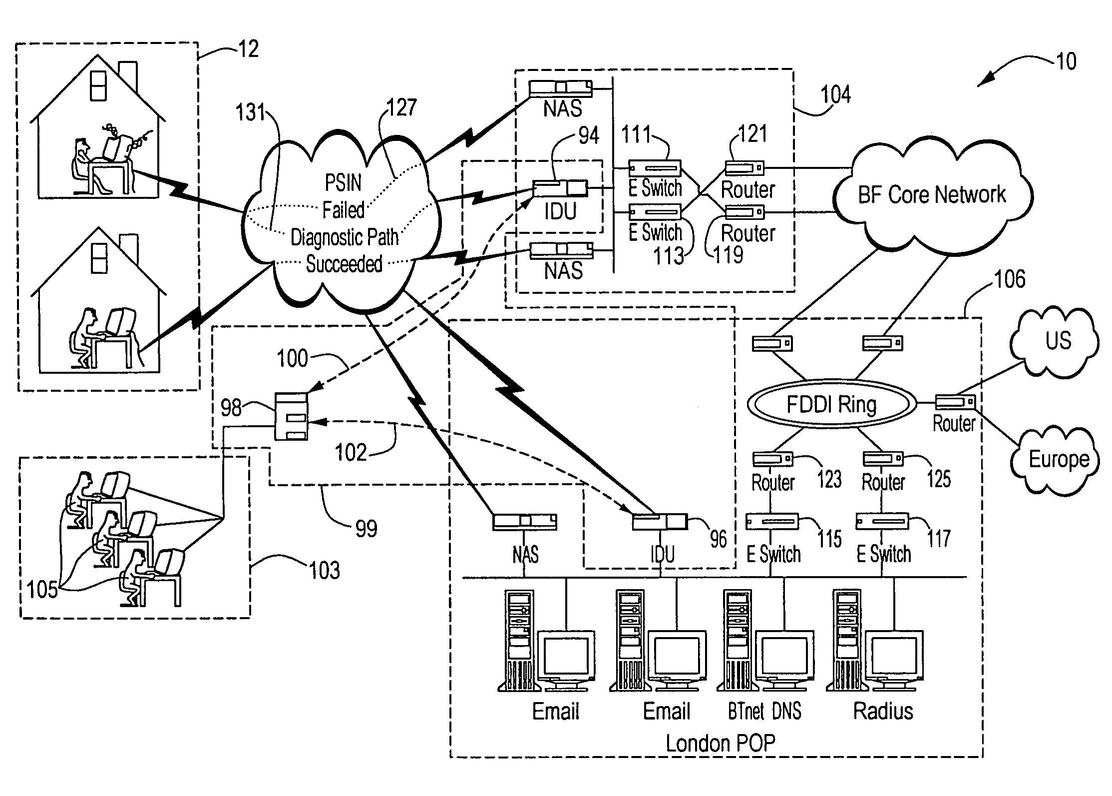
[0020]Various aspects of the invention may provide one or more of the following advantages. Faults can be isolated across a heterogeneous network at various, if not all, protocol layers as identified by the International Organization for Standardization (ISO) model standard number ISO 7498. Faults can be isolated without knowledge of network topology, or updating of knowledge of network topology. Where network topology information is required for fault isolation, network topology can be determined using automated topology discovery algorithms. Repair of isolated faults can be verified. Rule-based reasoning, case-based reasoning, machine learning, fault graphs and other diagnostic knowledge representation techniques from the domain of artificial intelligence can be used to isolate faults. Determined causes of faults can be used to improve the fault-isolating knowledge. Faults in a network can be isolated by a single, integrated system. Active test components can be used to isolate faults by, e.g., injecting test data into a network. Faults can be isolated with more comprehensive automated analysis and more accuracy than passively collecting data and analyzing the passively-collected data. Faults can be isolated quickly and with little or no involvement by support personnel. Fault isolation tests can be performed looking in to a network, away from a user, or looking out from a network, toward the user. These tests can be performed independently of the configuration or operation of the user, or network, respectively. Communication with a network user is possible even if the user's protocol and / or configuration is somehow improper, inhibiting communication with other portions of the network. Adaptations can be made to a network user's improper protocol and / or configuration. The user and / or the network can be emulated to the other. Fault isolation testing can be performed under centralized control. Fault isolation testing at multiple points in a network can be coordinated such that, e.g., tests can be performed simultaneously, and the impact of test data injected into a network at one point in the network can be determined at another point in the network. Fault isolation can be expert-system based. Network users can have faults, causing the user problems, isolated with or without assistance by support personnel. Complex network interactions can be reduced to simple information. Users can be informed as to remedial actions to correct faults causing the user problems, and can be informed of completion of the remedial actions. Network uptime, reliability, performance, and response / repair time can be improved. Symptoms and their root causes can be plotted for determining causes to be targeted for occurrence / cost reduction. Symptoms and their root causes can be monitored to determine improvements in occurrence / cost reduction of symptom-cause combinations.

Problems solved by technology

Indicating the problem can include the user attempting an interaction which results in a failure when sent to the network, to the network diagnostic unit instead.

Method used


Image

  • Network fault isolation
  • Network fault isolation
  • Network fault isolation

Examples


Embodiment Construction

[0028]The invention provides techniques for improved fault isolation and fault reduction. Diagnostic devices can be placed throughout a communications network under centralized control. These diagnostic devices can communicate with a user terminal, to determine a problem or symptom experienced by a user, e.g., when trying to transmit or receive data, even if the user terminal cannot communicate using a proper protocol or using a protocol improperly for desired network interactions. Problems or symptoms are what the user reports as evidencing a fault in the network. Faults can also be called causes or root causes. Through communications with the user and other portions of the network, the diagnostic devices, with help from the centralized control if needed, can isolate faults in the network and indicate and record the faults and remedial action and initiate the remedial action. The faults can be monitored and action taken to reduce the frequency at which faults occur. The diagnostic ...


PUM


Abstract

Techniques are provided for improved fault isolation and fault reduction. A system for use with a data network includes multiple diagnostic units each adapted to communicate with the network including to a network user. A central controller is operatively connected to the diagnostic units, the controller being adapted to communicate with and coordinate operations of the diagnostic units, to instruct the diagnostic units to perform tests adapted to help isolate a network fault, and to analyze test results received from a diagnostic unit to attempt to determine the network fault. Various methods for improving fault isolation and fault reduction are also provided.

Description

RELATED APPLICATIONS[0001]This application is a divisional application of copending U.S. application Ser. No. 09 / 322,107, filed May 28, 1999.BACKGROUND OF THE INVENTION[0002]The invention relates to networks such as communication and data networks and more particularly to isolating faults in such networks.[0003]Communication and data networks are rapidly growing in use and complexity. For example, the number of persons using the Internet to transmit and receive data grows on a daily basis. Also, the persons using the Internet are using it more as more websites are added, and as users become comfortable using more services available on-line such as buying goods, instead of just accessing information. The addition of sources of information and services, such as the ever-increasing number of websites, increases the complexity of the Internet. As the use and complexity of networks increases, so does the number of problems experienced by users.[0004]Network service providers want to redu...

Claims


Application Information

Patent Timeline
IPC IPC(8): G06F15/173G06F11/00G06F13/10G06F15/16G06F9/44G06F13/00H04L12/56H04L69/40H04Q3/00
CPCH04L12/2602H04L12/2697H04L41/0631H04L41/0659H04Q3/0075H04L43/50H04L43/00H04L43/0811H04L43/10
Inventor KAFFINE, DAVID M.SCHMIDT, PETER H.ROSEN, JOSEPH S.WOLF, JONATHANMELLOR, ARTHUR
Owner TERADYNE
Learn More