Integrated frequency translation and selectivity with gain control functionality, and applications thereof
a frequency translation and gain control technology, applied in the field of frequency translation and frequency selectivity, can solve the problems of limited tuning capabilities, interference with signals at desired frequencies, and difficult realization of high q factors at high frequencies using conventional filter techniques, and achieve the effect of precise frequency selectivity
- Summary
- Abstract
- Description
- Claims
- Application Information
AI Technical Summary
Benefits of technology
Problems solved by technology
Method used
Image

Examples
first embodiment
3.3.1 First Embodiment
Band Pass Filtering and Frequency Translation
[0258]An example embodiment of the invention, wherein band-pass filtering and frequency translation are performed, is described in the following sections.
3.3.1.1 Operational Description
[0259]A representation of a transfer function for a band-pass filter is shown in EQ. 3, which was discussed above and presented below for convenience. As indicated above, EQ. 3 is described herein for illustrative purposes only, and is not limiting.
VO=α1z−1VI−β1z−1VO−β0z−2VO EQ. 3
[0260]As evidenced by EQ. 3, the output signal VO is formed from a summation of scaled delayed values of the input signal VI and scaled delayed values of the output signal VO. More particularly, at any given time t, the value of the output signal VO is equal to a scaled value of the input signal VI from time t−1, minus a scaled value of the output signal VO from time t−1, minus a scaled value of the output signal VO from a time t−2.
[0261]It is noted that EQ. ...
second embodiment
3.3.2 Second Embodiment
Low Pass Filtering and Frequency Translation
[0277]An example embodiment of the invention, wherein low-pass filtering and frequency translation are performed, is described in the following sections.
3.3.2.1 Operational Description
[0278]EQ. 6 is a representation of a transfer function for a low-pass filter. EQ. 6, first introduced above, is presented below for convenience. As indicated above, EQ. 6 is described herein for illustrative purposes only, and is not limiting.
VO=α0z−2VI−β1z−1VO−β0z−2VO EQ. 6
[0279]As evidenced by EQ. 6, a low-pass filtering operation can be achieved by adding a scaled instance of the input signal VI that has been delayed by two time units to two scaled instances of the output signal VO that had been delayed by one and two time units, respectively.
[0280]Note that the low-pass transfer function of EQ. 6 is not in any way related to the frequency translation operation 1204. However, the invention preferably operates such that frequency tra...
third embodiment
3.3.3 Third Embodiment
Filtering with Mid-Point Injection and Frequency Translation
[0299]The UDF embodiments described above are provided for illustrative purposes only. The invention is not limited to these embodiments.
[0300]For example, as will be appreciated by persons skilled in the relevant art(s), it is possible to achieve a given set of filter characteristics using a variety of transfer functions. The elements of such transfer functions can be arranged and configured to satisfy particular goals and / or requirements.
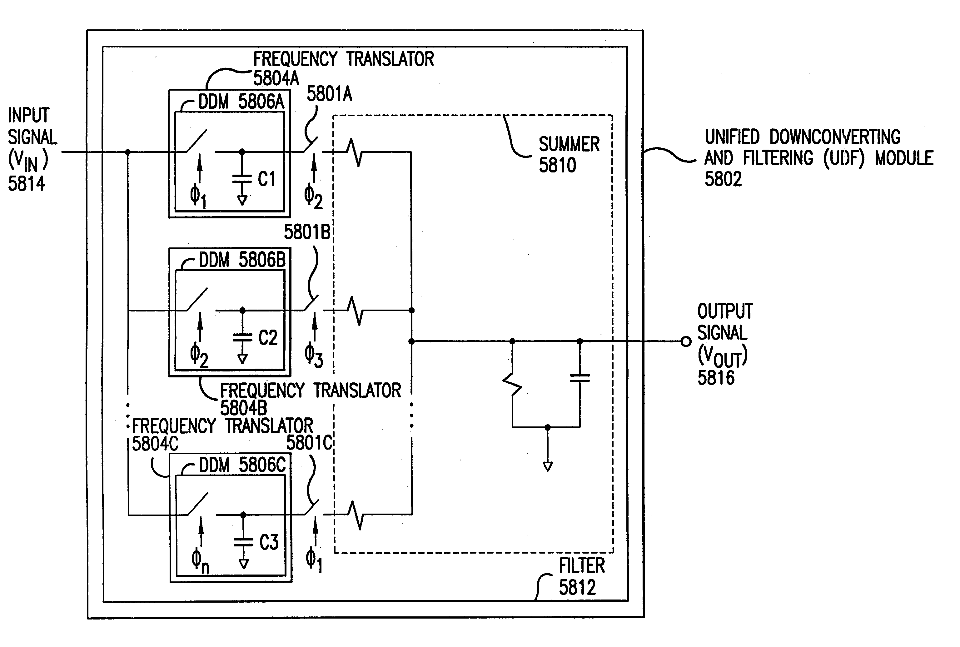
[0301]In a similar manner, a variety of UDF embodiments are possible. In such embodiments, components contained therein are selected and arranged to satisfy particular goals and / or requirements.
[0302]For example, and without limitation, it is possible to construct a UDF module 4402 having the operational map illustrated in FIG. 44. Such operation is herein characterized as filtering with mid-point injection, in combination with frequency translation. These embodiment...
PUM
 Abstract
Description
Claims
Application Information
 - R&D
- Intellectual Property
- Life Sciences
- Materials
- Tech Scout
- Unparalleled Data Quality
- Higher Quality Content
- 60% Fewer Hallucinations
Browse by: Latest US Patents, China's latest patents, Technical Efficacy Thesaurus, Application Domain, Technology Topic, Popular Technical Reports.
© 2025 PatSnap. All rights reserved.Legal|Privacy policy|Modern Slavery Act Transparency Statement|Sitemap|About US| Contact US: help@patsnap.com