Motor controller
a technology of motor controller and control panel, which is applied in the direction of motor/generator/converter stopper, dynamo-electric converter control, dynamo-electric gear control, etc., can solve the problems of increasing the size and reducing the cost of the device, and reducing the configuration of power semiconductor elements. , the effect of reducing the cost and size of the apparatus
- Summary
- Abstract
- Description
- Claims
- Application Information
AI Technical Summary
Benefits of technology
Problems solved by technology
Method used
Image
Examples
first embodiment
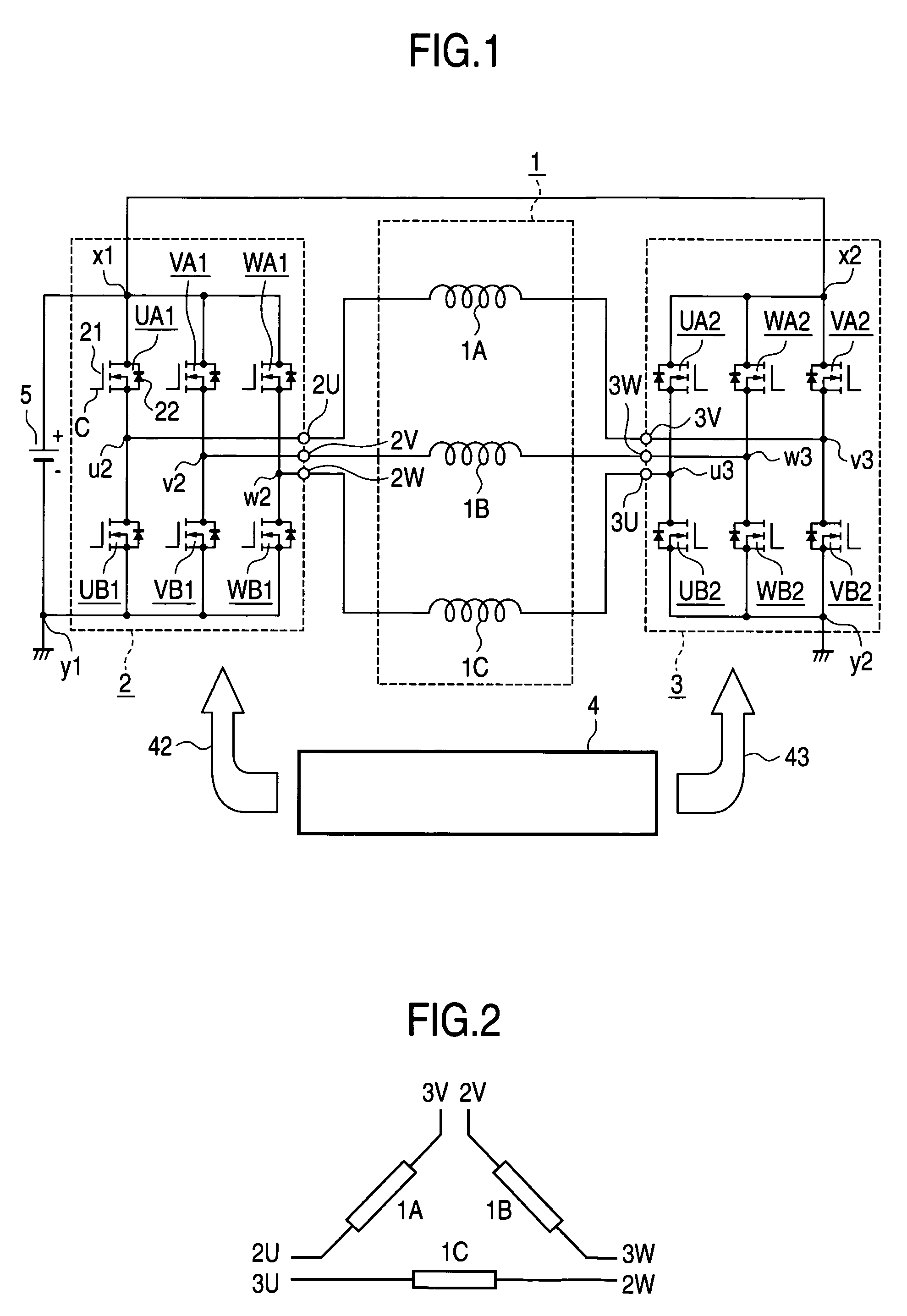
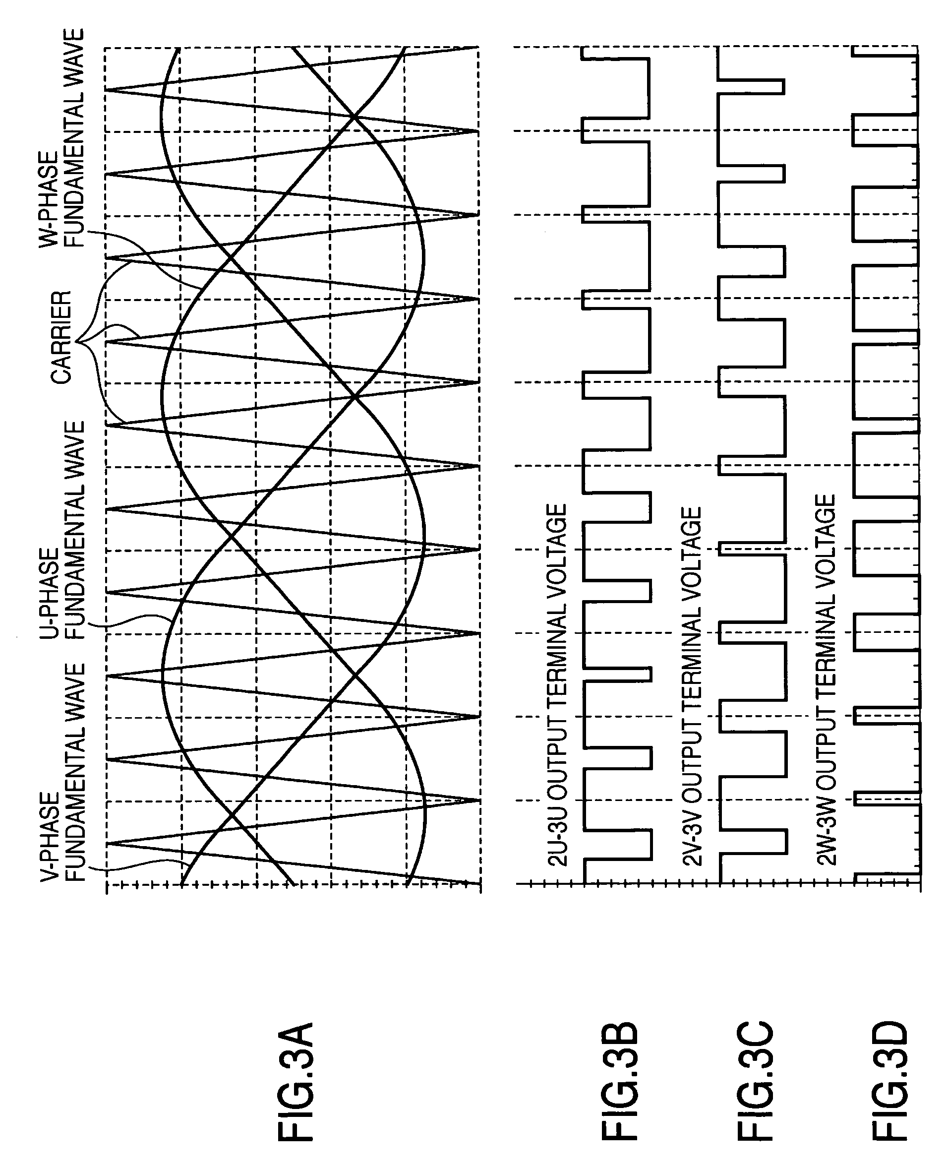
[0028]FIG. 1 shows a system configuration of a motor controller according to a first embodiment of the present invention. This system is configured as an electric motor generator having not only a function as an electric motor realizing so-called idle stop / start, say, automatically stopping the engine upon stopping the automobile and automatically operating it at a start thereof but also a function as the existing automotive alternator. The motor controller of the invention includes a motor 1 having stator windings 1A, 1B, 1C, inverter circuits 2, 3 for driving the motor 1, a control circuit 4 for forming a gate signal with which the two inverter circuits 2, 3 are controlled in operation, and a battery 5 which is a power source for driving the motor 1 and to which the generation energy is regenerated. The three-phase motor windings 1A, 1B, 1C are made opened at both ends, i.e. the both ends of the windings are extended out of the motor without providing a Δ-connection or a Y-connect...
second embodiment
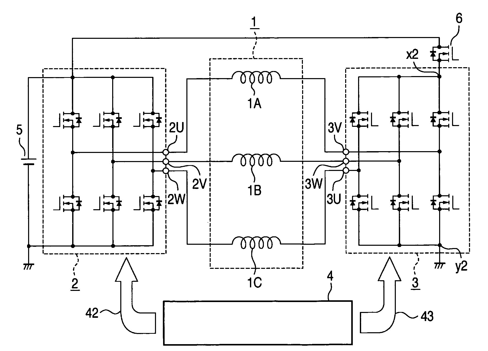
[0046]FIG. 12 shows a configuration of a motor controller according to a second embodiment of the invention. In the figure, like or corresponding elements are attached with like references. The difference from the first embodiment lies only in that a changeover switch 6 is inserted between a battery “+” side input terminal x2 of the switch block of an inverter circuit 3 and the “+” terminal of the battery 5. In the second embodiment, the changeover switch 6 is structured by a MOSFET.
[0047]The operation of the controller is now described separately upon powering and during power generation. First of all, a high voltage signal is inputted from the control circuit 4 to a control terminal of the changeover switch 6, to maintain the switch on. This state is similar in state to the first embodiment and hence omitted to explain because the operation is similar, wherein operation and effect is similar to that of the first embodiment.
[0048]The operation in power generation is now described. ...
third embodiment
[0053]FIG. 16 shows a configuration of a motor controller according to a third embodiment of the invention, wherein like or corresponding elements to those of FIG. 12 are attached with like references. This embodiment is effective for the case powering (idle starting) torque is required only in a low rotation range. The difference from the second embodiment lies only in that the inverter circuit 3 is replaced with a switch unit 7 wherein the signal for controlling it is a control signal 47 for the switch unit 7.
[0054]The switch unit 7 is configured with a parallel connection of three blocks (WA2 and WD7, VA2 and VD7) wherein a series connection of a semiconductor switch element UA2 having one control terminal and a diode UD7 is taken as one block. The semiconductor switch element UA2, WA2, VA2 is configured with a parallel connection of a MOSFET 71 and a diode 72 (true for other blocks). The diode 72 connected parallel may use a parasitic diode formed within the MOSFET 71.
[0055]With...
PUM
 Abstract
Description
Claims
Application Information
 - R&D
- Intellectual Property
- Life Sciences
- Materials
- Tech Scout
- Unparalleled Data Quality
- Higher Quality Content
- 60% Fewer Hallucinations
Browse by: Latest US Patents, China's latest patents, Technical Efficacy Thesaurus, Application Domain, Technology Topic, Popular Technical Reports.
© 2025 PatSnap. All rights reserved.Legal|Privacy policy|Modern Slavery Act Transparency Statement|Sitemap|About US| Contact US: help@patsnap.com


