
Lamp assembly with LED light sources including threaded heat conduction base

a technology of led light source and heat conduction base, which is applied in the direction of discharge tube/lamp details, signalling/lighting devices, and discharge tube/lamp details, etc., can solve the problems of reducing the effective range of infrared beams, and contributing significantly to production costs. , to achieve the effect of wide light coverage, short light illumination range and high thermal conductivity

Inactive Publication Date: 2007-10-16
TAIWAN GIGANTIC LIGHT ELECTRIC ,
View PDF7 Cites 15 Cited by
  • Summary
  • Abstract
  • Description
  • Claims
  • Application Information

AI Technical Summary

Benefits of technology

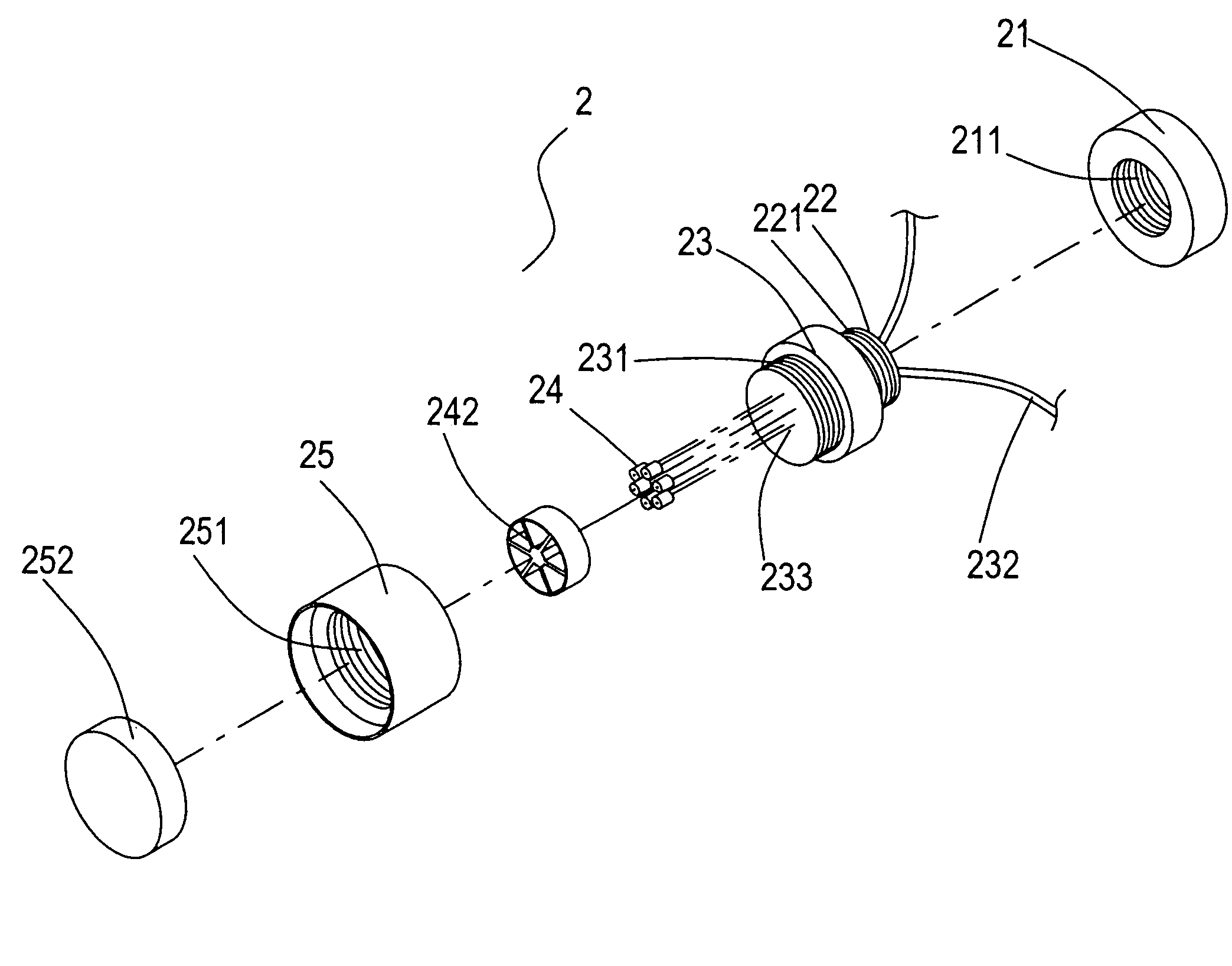
[0006]The primary objective of the present invention is to provide an LED light source using light emitting diode (LED) as the light emitting mechanism and being applied to surveillance cameras as an infrared source or a visible-light source. The infrared chip is powered by DC-current wires and mounted on a metallic heat sink with high thermal conductivity and made of copper, gold, silver or aluminum. The surface of the heat sink on which the chip is mounted can be planar for scattering light or convex for collimating light. In the case of a light-scattering planar surface, the range of light illumination is short and the light coverage is wide. As the surface is convex, the light is collimated and therefore has a longer illuminating distance. Further, the heat produced in the infrared chip can be transferred quickly through the much more massive metallic heat sink, whereby the temperature of the chip is significantly reduced. The heat is then conducted to a heat-conduction base and then to the ambient atmosphere. Therefore the chip can sustain a higher current and can have a higher light intensity.
[0007]The heat sink body has a plurality of elongated heat conducting members, each of which is a copper pin in a preferred embodiment. Those copper pins are then confined by an insulating bracket and then attached to the heat-conduction base. The metallic base can be coupled with a heat radiator to enhance heat radiation.
[0008]A secondary objective of the present invention is to provide an LED light source further comprising a lampshade made of aluminum alloy, which has a smooth and convex inner wall for reflecting and collimating the LED light. The lampshade can be secured with the heat-conduction base and form a part of the protective outer shell and an extra heat radiating part for the heat-conduction base. Therefore, the present invention can tolerate high LED operating power and high external impact.
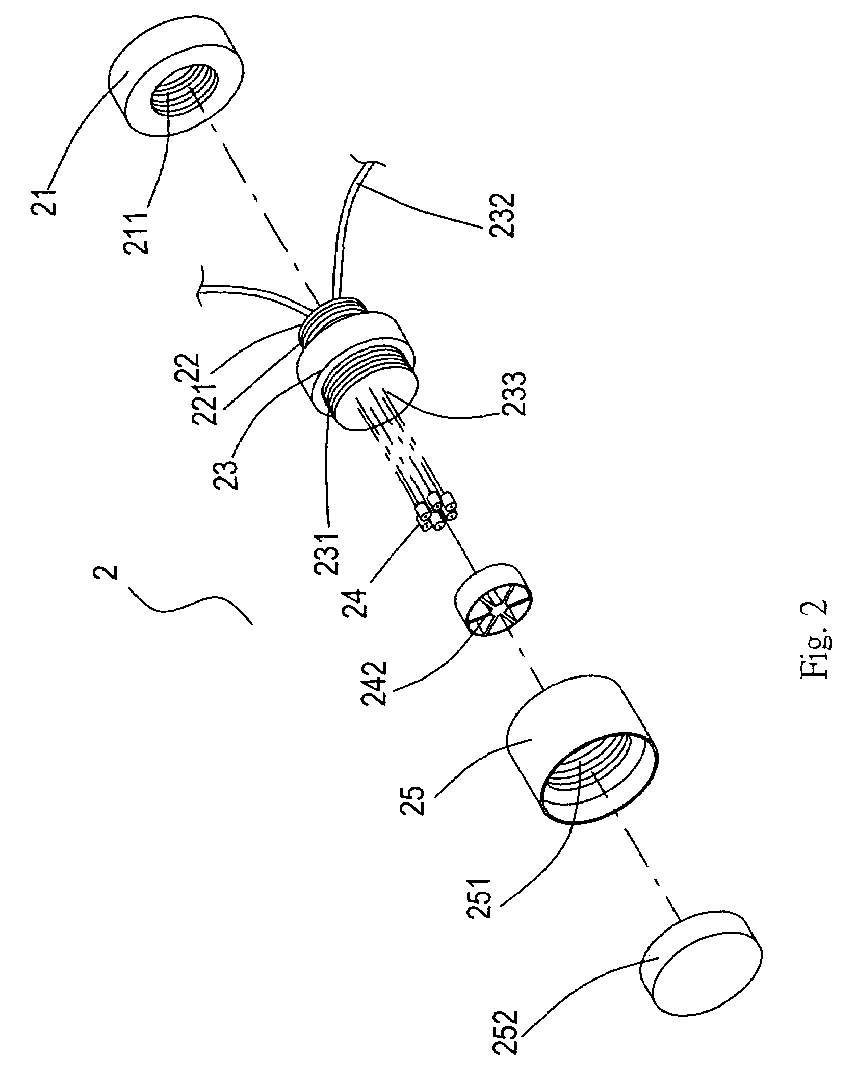
[0009]To achieve the above objectives, the LED light source comprises a base shell, wires, infrared light base, heat-conduction base, a heat sink body having a plurality of elongated heat conducting members, sink frame, lampshade and a lens. The inner wall of the base shell is provided with a screw thread for engaging a screw thread on the outer wall of the infrared light base, thereby preventing damaging the screw thread and securing the base shell. The inner rim of the lampshade is provided with a screw thread for engaging the screw thread of the heat-conduction base, whereby the lampshade can form a part of the outer shell of the light source for protecting the LEDs therein. The front end of the lampshade is provided with the lens for preventing dust infiltration.

Problems solved by technology

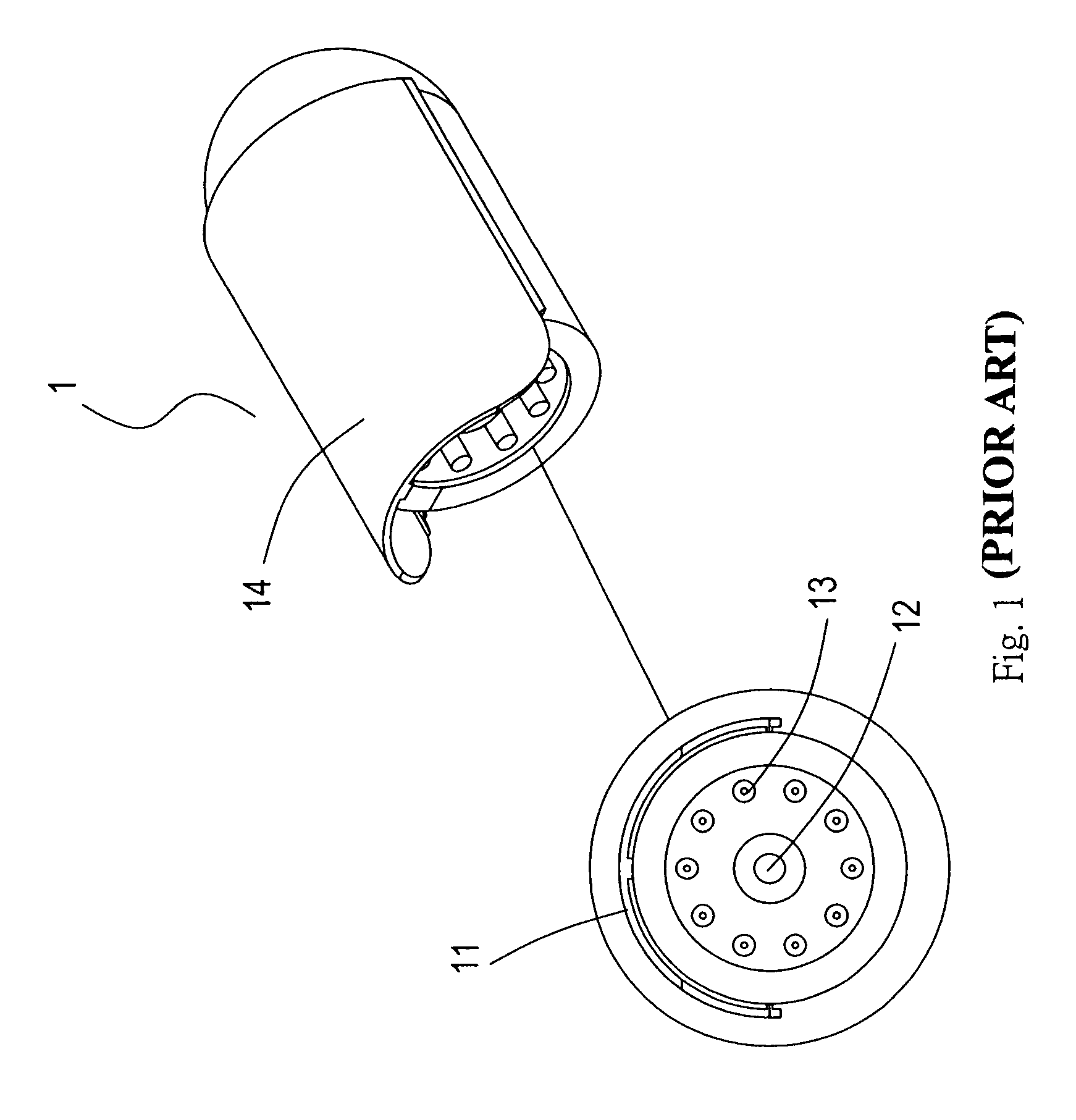
Since a significant amount of infrared emitters 13 are needed in such a conventional device, they occupy the majority of the camera space, therefore contributing significantly to the production cost.
Further, the beam intensity of the infrared emitters 13 is so limited that the effective range for the infrared beam is short.
To use as a light source, a multitude of LEDs are needed to attain a practical light intensity, which occupy a significant amount of space and therefore increases the production cost.
Further, the clustering of LEDs results in heat radiation problem, which in turn causes overheating of the light source and may result in damage of the chips in the LEDs and blurring of the transparent enclosure.
Basically, a light source using a closely packed cluster of LEDs would have problems in durability and light intensity, both increasing the cost of using such light sources.

Method used


Image

  • Lamp assembly with LED light sources including threaded heat conduction base
  • Lamp assembly with LED light sources including threaded heat conduction base
  • Lamp assembly with LED light sources including threaded heat conduction base

Examples


Embodiment Construction

[0020]Referring to FIGS. 2, 3, and 4, an LED light source 2 according to the present invention comprises a base shell 21, wires 232, infrared light base 22, heat-conduction base 23, a heat sink body having a plurality of elongated heat conducting members 24, sink frame 242, lampshade 25 and a protective lens 252. The inner wall of the base shell 21 is provided with a screw thread 211 for engaging a screw thread 221 on the outer wall of the infrared light base 22, thereby securing the base shell 21 and preventing damaging the screw thread 211. A set of wires 232 is disposed within the infrared light base 22 for powering the light emitting diode (LED). For absorbing heat conducted through the heat sink body 24 and dissipating to the outside, the heat-conduction base 23 is mounted at a front end of the infrared light base 22, larger in volume than the heat sink body 24. The heat-conduction base 23, made of copper, is provided with a screw thread 231 at the front end thereof. A supporti...


PUM


Abstract

An LED light source applied to surveillance cameras as an infrared source or a visible-light source has a light emitting diode (LED) as the light emitting mechanism. The LED chip is mounted on a surface of a metallic body of high thermal conductivity, the surface being planar for scattering light or convex for collimating light. The heat produced in the LED chip is quickly guided to a heat-sink structure much massive than the chip and having large contact area with a heat radiating structure, thereby effectively dissipating the heat and increasing the power capacity of the chip. The heat-sink structure has a plurality of elongated heat conducting members confined by an insulating bracket at one end and mounted on a metallic base on the other end. The metallic base can be coupled with a heat radiator to enhance heat radiation.

Description

FIELD OF THE INVENTION[0001]The present invention related to LED light sources, more particularly to an LED light source wherein the light source is a light emitting diode and has a metallic heat sink of high thermal conductivity. At the top end of the heat sink, an infrared LED chip is disposed. The surface, on which the chip attached to, can be planar for scattering light or convex for collimating light. The heat produced in the chip is absorbed quickly and conducted away by the heat sink so that the temperature of the chip can be limited. The heat is further conducted through a heat-conduction base (made of copper or aluminum), to a heat radiator and then to the ambient atmosphere.[0002]The LED light source further comprises a lampshade made of aluminum alloy, which has a smooth and convex inner wall for reflecting and collimating the LED light. The lampshade can be secured with the heat-conduction base and form a part of a protective shell and an extra heat radiating part for th...

Claims


Application Information

Patent Timeline
Patent Type & Authority Patents(United States)
IPC IPC(8): H01L33/00F21V19/00F21V29/00F21K99/00
CPCF21V29/89F21V29/70F21V29/74F21V29/77F21K9/30F21Y2101/02Y10S362/80F21V33/0076F21K9/20F21Y2115/10
Inventor LI, CHIA MAO
Owner TAIWAN GIGANTIC LIGHT ELECTRIC ,
Learn More