Pumping method for laser equipment
a laser equipment and pumping technology, applied in the direction of laser details, laser arrangement, active medium materials, etc., can solve the problems of hindering high-efficiency amplification, difficult multiplication of amplification stages, complicated amplifier design, etc., and achieve the effect of efficient amplification
- Summary
- Abstract
- Description
- Claims
- Application Information
AI Technical Summary
Benefits of technology
Problems solved by technology
Method used
Image
Examples
embodiment 1
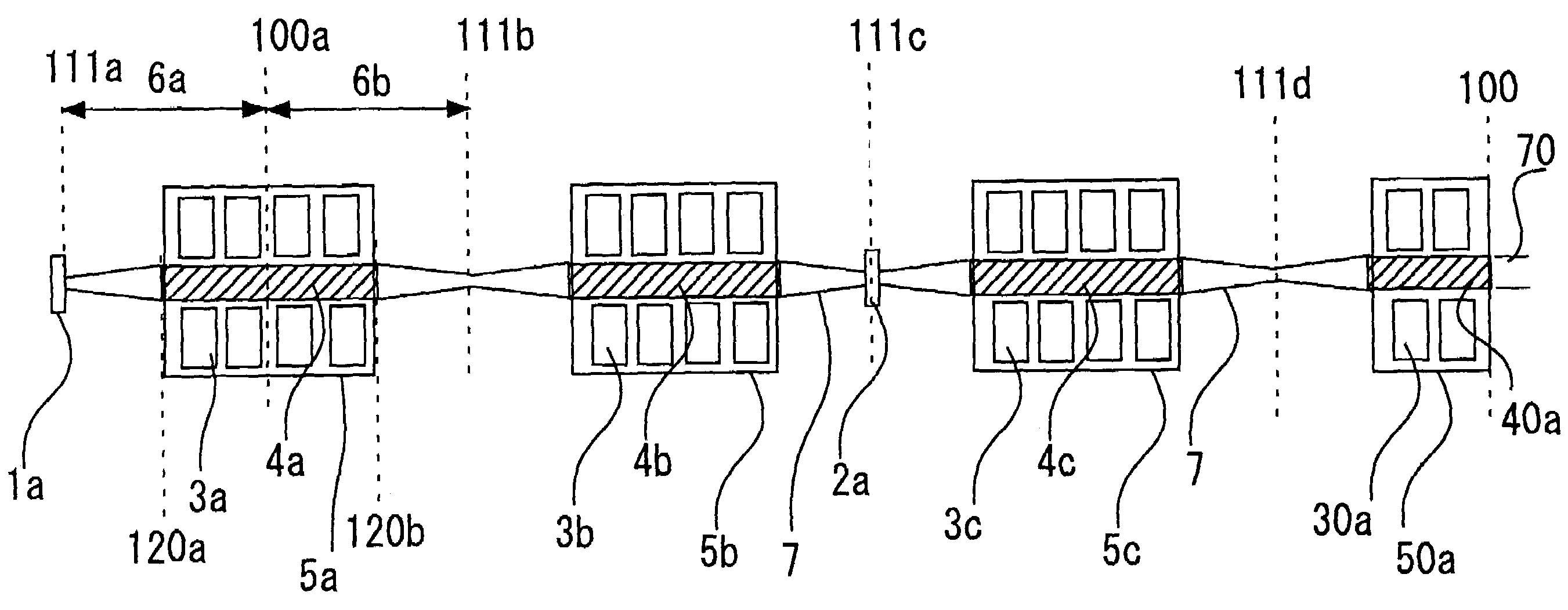
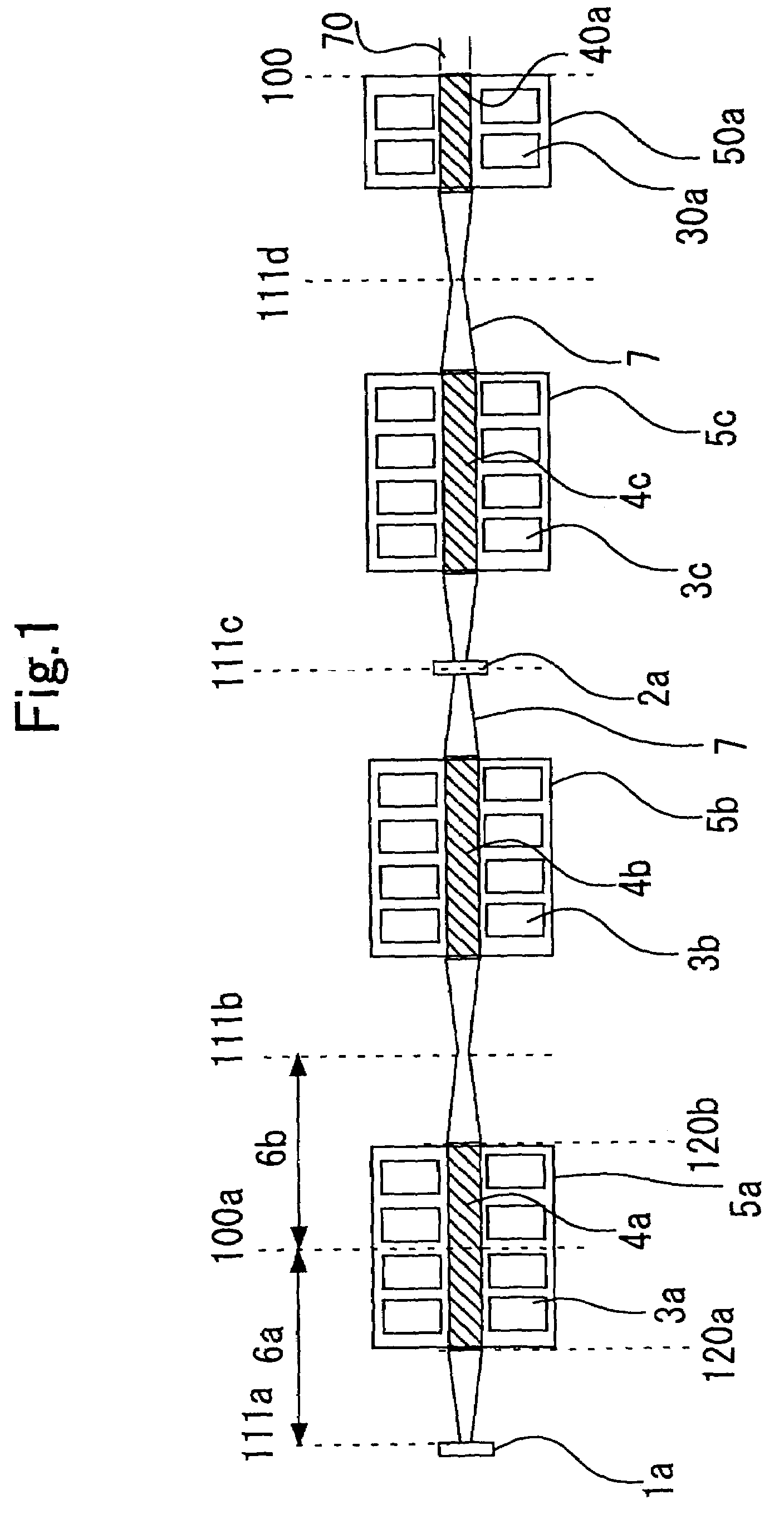
[0064]FIG. 1 is a view for explaining laser equipment and its pumping method according to Embodiment 1 of the present invention, and more particularly is a block diagram of the laser equipment. In FIG. 1, 1a is a totally reflecting mirror with a plane curvature; 2a is a partially transmitting mirror with a plane curvature; 3a, 3b, 3c and 30a are laser-active-media-pumping devices such as LD (Laser diodes) and lamps; 4a, 4b, 4c and 40a are rod-type solid-state laser active media made of Nd YAG; 5a, 5b, 5c and 50a are laser pumping sections. A laser oscillator is constituted by arranging two laser pumping sections 5a and 5b between the totally reflecting mirror 1a and the partially transmitting mirror 2a. In addition, two other laser pumping sections 5c and 50a are arranged as an amplifier outside the laser oscillator 50a is the laser pumping section arranged at the output end and includes the laser active medium 40a and the laser-active-medium pumping device 30a.
[0065]Three laser pu...
embodiment 2
[0083]FIG. 11 is a view for explaining laser equipment and its pumping method according to Embodiment 2 of the present invention, and more particularly, is a schematic diagram illustrating laser pumping sections, i.e., FIG. 11 is an example of constitution of the laser pumping sections 5c and 50a in Embodiment 1, with LDs (laser diodes, i.e., a semiconductor laser) as pumping sources. Among the regions in the beam-axis direction of laser active media, in FIG. 11, only the portions illustrated as regions D1, D2, and E are excited, and the excited region D is divided into two regions D1 and D2. 130a is the end position of the excited region of the laser active medium 4c, and 102 is an end position of the excited region of the laser active medium 40a. Moreover, 10d is an end position of the laser active medium 40a.
[0084]In the embodiment illustrated in FIG. 11, the excited region of the laser active medium 4c is divided into two portions D1 and D2. Also in this situation, a beam-extra...
embodiment 3
[0089]FIG. 12 is a view for explaining laser equipment and its pumping method according to Embodiment 3 of the present invention, and more particularly is a block diagram illustrating the laser equipment. In FIG. 12, 25 is a laser-beam-return mirror having high reflectance to an infrared beam with an incident angle of 45 degrees; 26 is a power meter; 27 is a commercially available beam monitoring device that can monitor the distance between its own position and the position where the wavefront curvature of a laser beam is infinite, and the beam diameter in that particular position.
[0090]Demonstrative experiment according to the present invention, which was carried out with laser equipment that utilized the side-LD-pumping type Nd: YAG rod laser and was constituted as shown in FIG. 12, is set forth hereinafter. In the laser pumping sections 5a and 5b, 16 LDs (laser diodes) 3a and 3b, which are laser-active-medium pumping devices, are arranged so as to form four rows along the beam-ax...
PUM
 Abstract
Description
Claims
Application Information
 - R&D
- Intellectual Property
- Life Sciences
- Materials
- Tech Scout
- Unparalleled Data Quality
- Higher Quality Content
- 60% Fewer Hallucinations
Browse by: Latest US Patents, China's latest patents, Technical Efficacy Thesaurus, Application Domain, Technology Topic, Popular Technical Reports.
© 2025 PatSnap. All rights reserved.Legal|Privacy policy|Modern Slavery Act Transparency Statement|Sitemap|About US| Contact US: help@patsnap.com


