Measuring method and instrument comprising image sensor

Active Publication Date: 2007-09-25
ARKRAY INC
View PDF16 Cites 6 Cited by
  • Summary
  • Abstract
  • Description
  • Claims
  • Application Information

AI Technical Summary

Benefits of technology

[0016]With this arrangement, it becomes possible to easily measure the reflection factor two-dimensionally or along a straight line.
[0020]Moreover, since the straight line connecting the pixel outputs of two points sandwiching the color-developing area of the measuring object, that is, a straight line connecting the pixel outputs of non-color-developing portions at both of the ends of the light-developing area, is set to a baseline value, it is possible to reduce variations in the intensity due to coloring of the measuring object as well as variations in the intensity due to the height and gradient of the measuring object.
[0033]With this arrangement, it becomes possible to easily carry out the density measurement of the measuring object such as an immuno-chromatograph test piece.

Problems solved by technology

In the case when the detection range is fixed to only the color-developing area, positional deviations of the measuring object give adverse effects to the detection intensity.
Moreover, if the intensity and area of the measuring object vary after the color development, deviations become greater in the measuring results.

Method used


Image

  • Measuring method and instrument comprising image sensor
  • Measuring method and instrument comprising image sensor
  • Measuring method and instrument comprising image sensor

Examples


embodiment 1

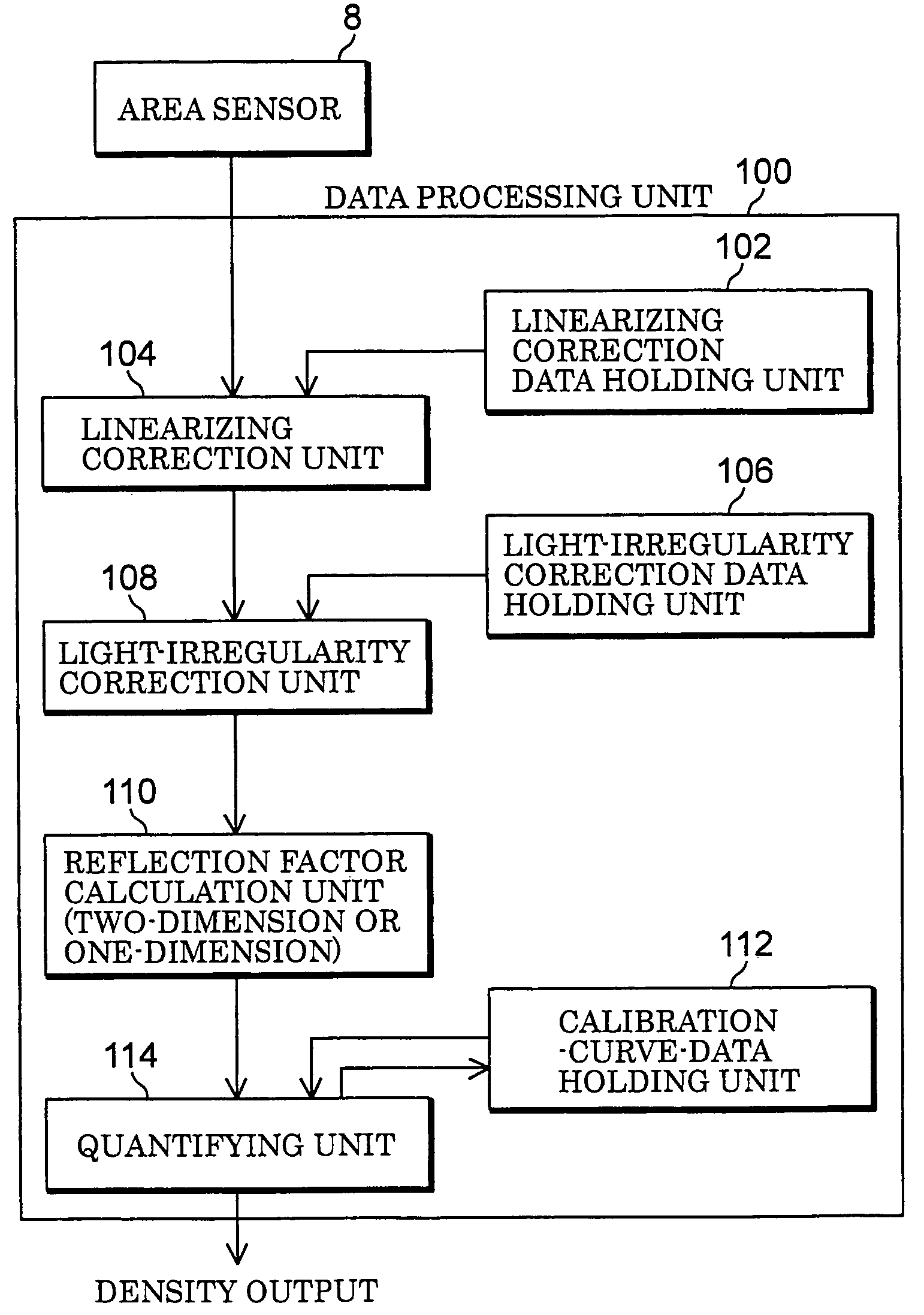
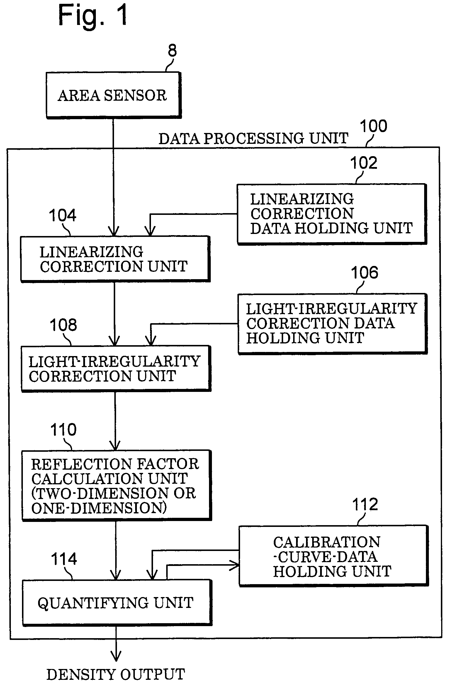
[0083]With respect to the first embodiment, the following description will discuss a two-dimensional reflection factor measuring device in which an area sensor is used as a sensor and to which the output correcting method in accordance with the first aspect of the present invention is applied.

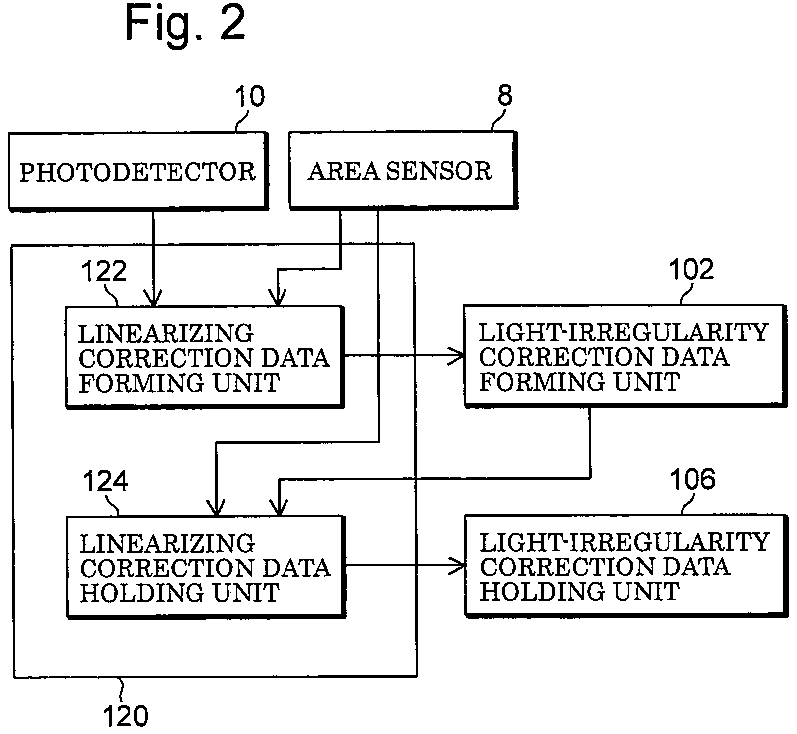
[0084]The linearizing correction data held in the linearizing correction data holding unit 102 and the light-irregularity correction data held in the light-irregularity correction data holding unit 106 may be generated by this reflection-factor measuring device or a test-piece measuring device. Therefore, as shown in FIG. 2, the measuring device is preferably further provided with a photodetector 10 which is placed at a position for receiving light reflected from a test piece held on a sample base, and has an output that has linearity with respect to the quantity of light to be received; a linearizing correction data forming unit 122 which forms linearizing correction data that is used for corr...

embodiment 2

[0177]With respect to a second embodiment of a reflection-factor measuring device, FIG. 16 shows one example to which an output correction method in accordance with the second aspect of the present invention is applied.

[0178]In comparison with the reflection-factor measuring device of FIG. 3, the present device is different in that a photodetector 10 for monitoring the quantity of light is not installed. The other structure is basically the same. Reflected light of a test piece 2 is converged on an area sensor 8a as an image by a lens 6 through a reflection plate 5. The area sensor 8a includes devices up to the amplifier 22 shown in FIG. 3. The detection signal of the area sensor 8a is taken into a calculation unit 28a through an A / D converter 24. This calculation unit 28a corresponds to the RAM 26 and the personal computer 28 in FIG. 3. A display device 30, a keyboard 32 and a printer 34 are connected to the calculation unit 28a. Reference numeral 36 represents an image storing uni...

embodiment 3

[0190]With respect to a third embodiment of a reflection-factor measuring device, the following description will discuss one example to which an output correction method in accordance with the third aspect of the present invention is applied.

[0191]Here, the optical system is the same as that shown in FIG. 16.

[0192]In this embodiment, the area sensor 8a is designed so that the exposing time during which the area sensor 8a receives light is programmable. With respect to such an image sensor, for example, a CMOS image sensor (H64283FP) made by Mitsubishi Electric Corporation, which is used in the embodiment shown in FIG. 3, may be used. However, not limited to CMOS image sensors, a CCD image sensor may be used as the area sensor 8a as long as it makes the exposing time programmable.

[0193]Although the output of the area sensor 8a does not have linearity with respect to the quantity of received light, the quantity of received light is directly proportional to the exposing time. Here, the...


PUM


Abstract

A linearizing correction unit (104) carries out a linearizing correction process on the output of an image sensor (8) based upon linearizing correction data stored in a linearizing correction data holding unit (102), and a light-irregularity correction unit (108) carries out a light-irregularity correction process on the image sensor output that has been subjected to the linearizing correction process based upon light-irregularity correction data stored in a light-irregularity correction data holding unit (106). A refection factor calculation unit (110) calculates an integral value of the in-plane reflection factor of a test piece by using the output that has been subjected to the linearizing correction and light-irregularity correction with respect to pixel outputs of the image sensor (8) obtained when the test piece having in-plane density irregularities is measured. A quantifying unit (114) applies calibration curve data of a calibration-curve-data holding unit (112) to the integrated reflection factor obtained by the reflection factor calculation unit so that a sample density of the test piece is calculated.

Description

FIELD OF THE INVENTION[0001]The present invention relates to a measuring method which applies light to a measuring object such as a test piece and carries out measurements two-dimensionally or along a straight line, by receiving light reflected from the test piece by an image sensor such as an area sensor and an image scanner, a measuring method for a measuring object which obtains a sample density of a detected portion based upon the measured value, and a device for achieving such a method.[0002]In the present invention, the light to be measured includes various kinds of light, such as reflected light, transmitted light, fluorescent light, phosphor light and chemically emitted light, which are used in quantitative measurements and qualitative measurements.BACKGROUND OF THE INVENTION[0003]Photodetectors include a photodetector element constituted by single elements such as a photodiode, a linear sensor constituted by photodetector elements that are aligned on a line, such as a photo...

Claims


Application Information

Patent Timeline
IPC IPC(8): G06K9/40G01J1/18G01J1/20G01J3/28G01N21/27G01N21/59
CPCG01J1/124G01J1/1626G01N21/274G01N21/5907G01N2021/5949G01N2021/5957
Inventor WADA, ATSUSIEGAWA, KOUJI
Owner ARKRAY INC
Why Eureka
Try Eureka