Extreme ultra violet light source device
a light source device and ultra-violet technology, applied in the field of light source devices, can solve the problems of reducing the reflectance, damage to the collection mirror, and reducing the life of the collection mirror, so as to reduce the running cost of the euv light source device, the collection mirror can be extended, and the effect of efficient collection
- Summary
- Abstract
- Description
- Claims
- Application Information
AI Technical Summary
Benefits of technology
Problems solved by technology
Method used
Image
Examples
first embodiment
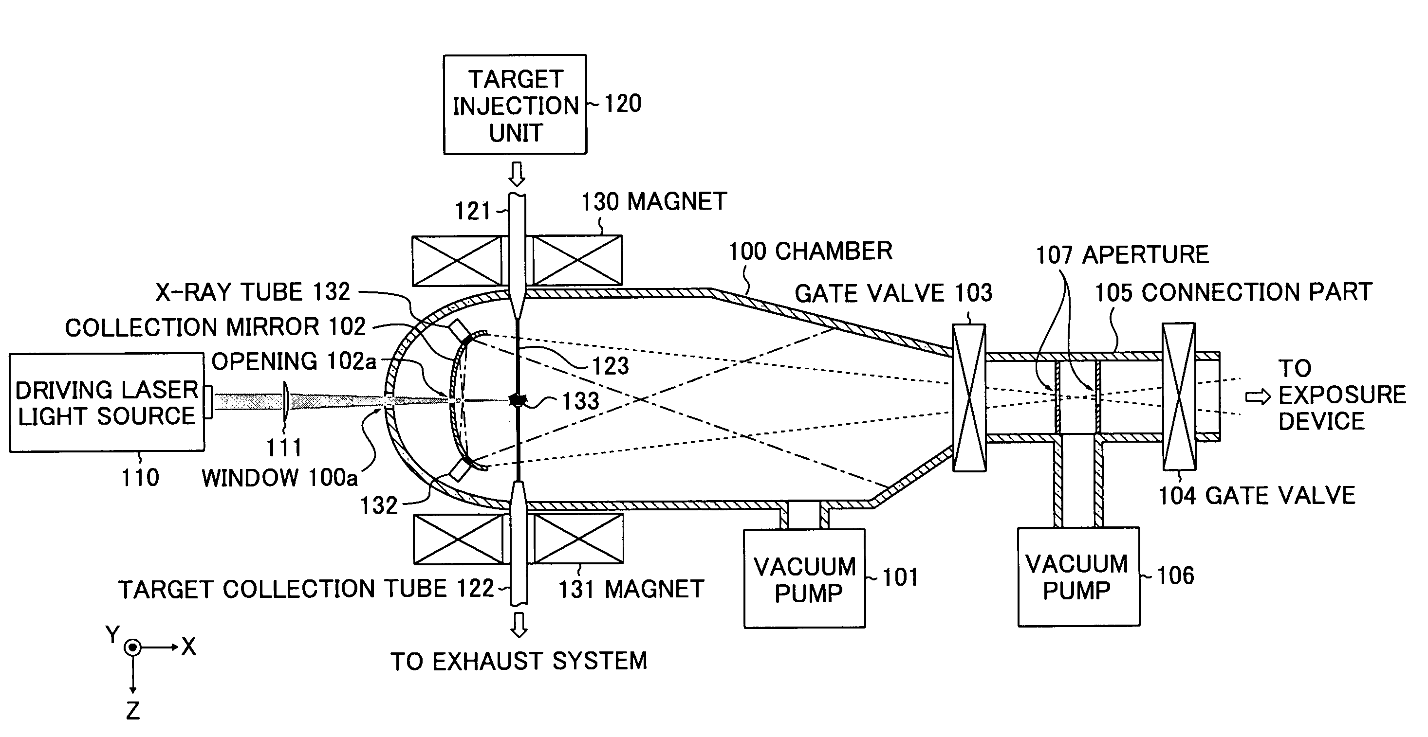
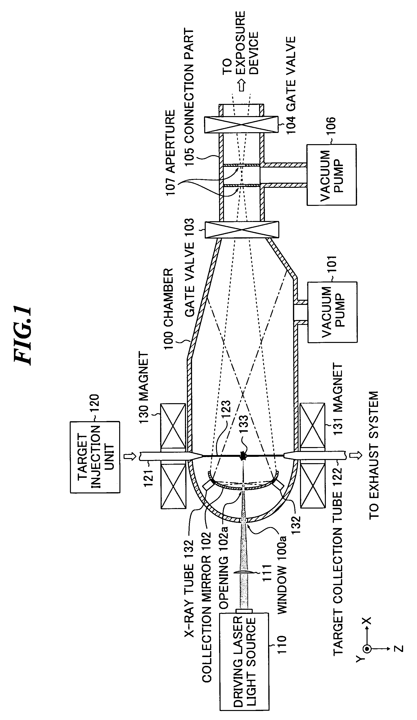
[0035]First, a basic configuration of an EUV (extreme ultra violet) light source device will be described by referring to FIG. 1. FIG. 1 is a schematic diagram showing a configuration of an extreme ultra violet light source device according to the present invention.
[0036]The EUV light source device shown in FIG. 1 includes a chamber 100, a driving laser light source 110 for generating a laser beam, an irradiation optical system 111 and a target injection unit 120. Further, in or near the chamber 100, a vacuum pump 101, a collection mirror 102, a target injection nozzle 121 and a target collection tube 122 are provided.
[0037]The air within the chamber 100 is exhausted by the vacuum pump 101, and thereby, maintained at a predetermined pressure.
[0038]The driving laser light source 110 generates a laser beam for providing energy to a target material for excitation. Further, the irradiation optical system 111 collects the laser beam generated from the driving laser light source 110 and i...
second embodiment
[0053]FIG. 4 is a schematic diagram showing a configuration of an EUV light source device according to the present invention. In the embodiment, the X-ray tubes 132 are provided between the EUV light generation plasma 133 and the collection mirror 102. Further, in the embodiment, the application directions of the respective X-ray tubes 132 are determined such that the EUV light generation plasma 133 comes to the end of the range of X-ray application in order to apply X-ray intensively to the space between EUV light generation plasma 133 and the collection mirror 102. The remaining configuration is the same as that of the EUV light source device shown in FIG. 1.
third embodiment
[0054]FIG. 5 is a schematic diagram showing a configuration of an EUV light source device according to the present invention.
[0055]In the above-mentioned first and second embodiments, the optical path of the laser beam, the orbit of the target material and the arrangement of the X-ray tubes 132 have been illustrated in the same plane, however, they are not necessarily in the same plane. For example, as shown in FIG. 5, the target material 123 may be injected toward the Y-direction (the direction from the back side to the front side of the paper). Further, in the embodiment, the application directions of the respective X-ray tubes are determined such that the central axes of the output X-rays lies the collection mirror in order to apply X-ray intensively to the space between EUV light generation plasma 133 and the collection mirror 102.
[0056]Next, variations in the arrangement of the plural X-ray tubes and magnets in the first to third embodiments of the present invention will be des...
PUM
 Abstract
Description
Claims
Application Information
 - R&D
- Intellectual Property
- Life Sciences
- Materials
- Tech Scout
- Unparalleled Data Quality
- Higher Quality Content
- 60% Fewer Hallucinations
Browse by: Latest US Patents, China's latest patents, Technical Efficacy Thesaurus, Application Domain, Technology Topic, Popular Technical Reports.
© 2025 PatSnap. All rights reserved.Legal|Privacy policy|Modern Slavery Act Transparency Statement|Sitemap|About US| Contact US: help@patsnap.com


