
Combinatorial screening system and X-ray diffraction and Raman spectroscopy

Active Publication Date: 2007-09-11
BRUKER AXS
View PDF12 Cites 29 Cited by
  • Summary
  • Abstract
  • Description
  • Claims
  • Application Information

AI Technical Summary

Benefits of technology

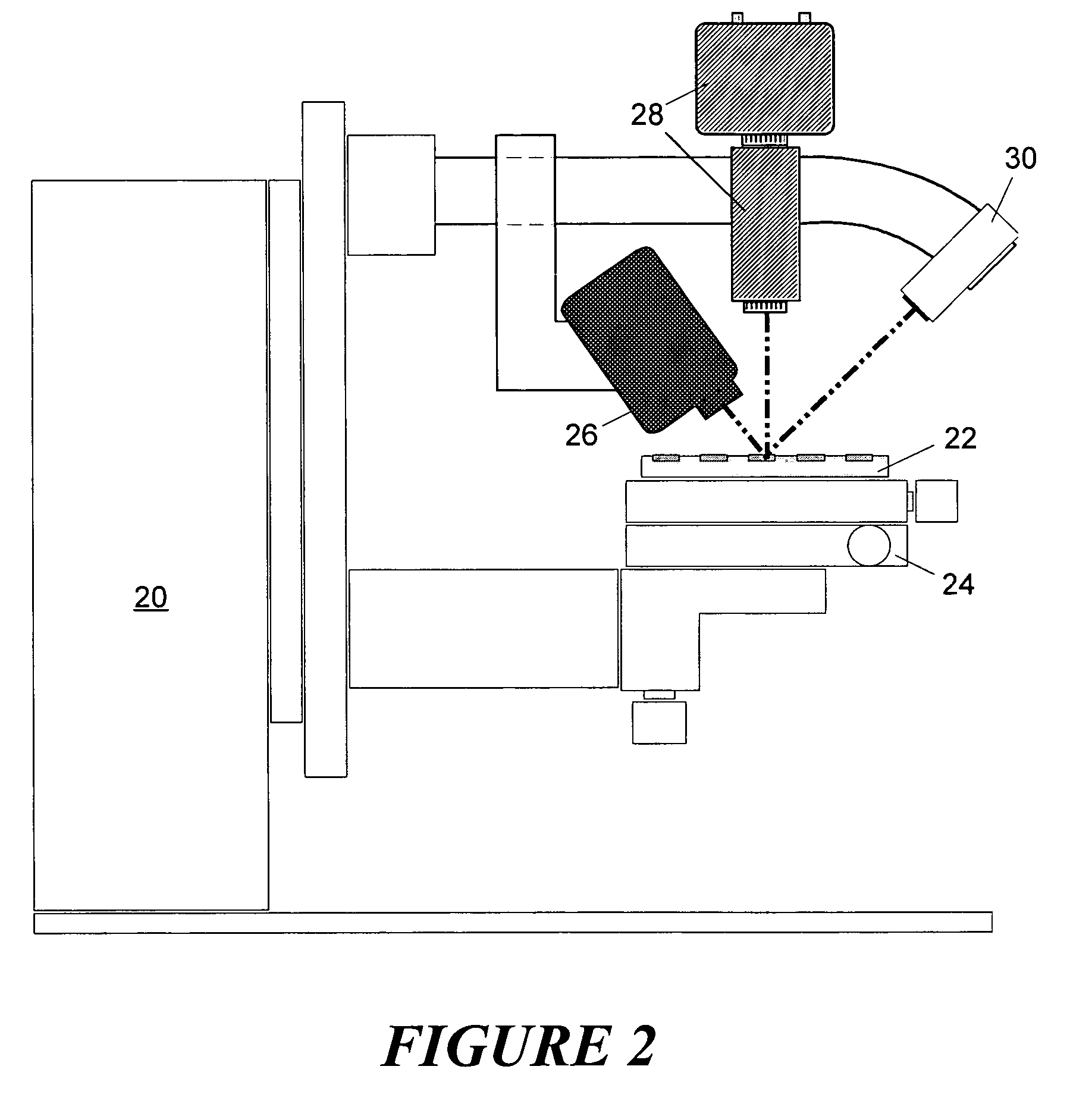
[0007]In an alternative embodiment of the invention, a knife edge is provided for use with X-ray diffraction screening. The knife edge may be positioned above the sample under test while it is being illuminated with X-rays. Since the X-ray source delivers X-ray energy along a direction that is at an acute angle relative to an upper surface of the sample library, the knife edge may thereby block X-ray energy from the X-ray source from reaching any adjacent samples, which could otherwise cause cross-contamination. In one version of this embodiment, the knife edge may be attached to the Raman probe, so that the two components move together. When the knife edge is positioned directly above the sample under test, the system is well arranged for X-ray diffraction analysis. The Raman probe and knife edge may then be moved together so that the knife edge is no longer above the sample under test, but so that the Raman probe is positioned above the sample under test. In this position, the system is well arranged for analysis by Raman spectroscopy. A third position of the knife edge / Raman probe combination could also be used in which both components are moved away from an area above the sample under test. If the video microscope was positioned above the sample under test at a position higher than that which might be occupied by the knife edge or Raman probe, the movement of those two components away from the region above the sample under test removes any visual obstruction to the video microscope. Visual data from the sample under test can then be collected, and used for sample analysis or sample positioning as necessary.
[0008]In yet another embodiment, the X-ray source and optics, the Raman probe and the laser video assembly can all be made to move in unison. For example, all three of these components can be connected to the inner circle of a goniometer which, when rotated, thereby results in the rotation of all of these components. This allows the components to have a fixed angular relationship relative to one another. It also allows the components to be give the same position and orientation relative to a sample under test when their respective data is collected.

Problems solved by technology

Since the X-ray source delivers X-ray energy along a direction that is at an acute angle relative to an upper surface of the sample library, the knife edge may thereby block X-ray energy from the X-ray source from reaching any adjacent samples, which could otherwise cause cross-contamination.

Method used


Image

  • Combinatorial screening system and X-ray diffraction and Raman spectroscopy
  • Combinatorial screening system and X-ray diffraction and Raman spectroscopy
  • Combinatorial screening system and X-ray diffraction and Raman spectroscopy

Examples


Embodiment Construction

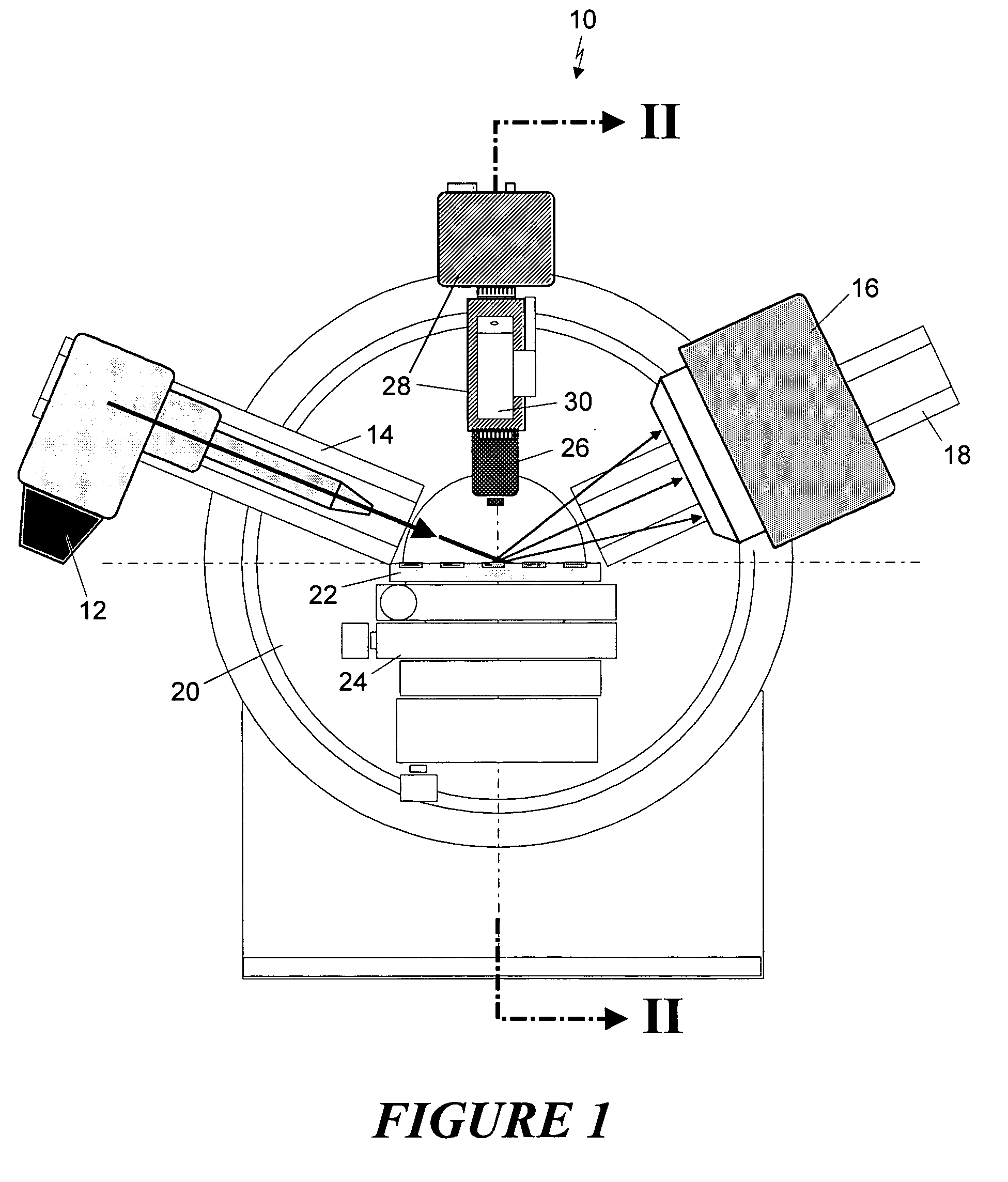
[0014]FIG. 1 is an illustration of the front view of a system consisting of an analysis system 10 that includes an X-ray diffractometer, Raman spectrometer and video microscope. In the system, the x-ray source and optics 12 are mounted on a dovetail track, referred to herein as θ1 track 14. A two-dimensional X-ray detector 16 is mounted on another dovetail track, referred to herein as θ2 track 18. θ1 track 14 is mounted to the inner circle of goniometer 20, while the θ2 track 18 is mounted on the outer circle of the goniometer. The sample library 22 is placed on an XYZ translation stage 24. The Raman probe 26, the video microscope 28 and the laser 30 are mounted on the stationary part of the goniometer 20.

[0015]The system shown in FIG. 1 is capable of collecting analytical data from a sample under test using several different techniques. The Raman probe 26 is located above the sample, and uses a laser source that delivers photonic energy to the sample, and a collection device that d...


PUM

PropertyMeasurementUnit
structureaaaaaaaaaa
energyaaaaaaaaaa
X-ray energyaaaaaaaaaa

Abstract

A sample analysis system makes use of both X-ray diffraction analysis and Raman spectroscopy of a sample. The sample is part of a sample library that is mounted on an XYZ stage that allows each sample to be examined in turn, as the XYZ stage is moved to position successive samples to a sample location. The system components may be mounted on a goniometer to allow their repositioning. A video system may be used for optical examination of the sample, and a knife edge may be used to prevent X-ray radiation from reaching a sample adjacent to the sample positioned at the sample location. A controller may be used to automatically control the operation of the analysis components and the movement of the sample holder to as to allow automated analysis of all of the samples in the sample holder.

Description

CROSS-REFERENCE TO RELATED APPLICATION[0001]This application takes priority from U.S. Provisional Patent Application Ser. No. 60 / 592,713, filed Jul. 30, 2004.FIELD OF THE INVENTION[0002]The present invention relates generally to analysis for combinatorial chemistry applications and, more specifically, to the use of a multi-faceted screening system for doing combinatorial analysis.BACKGROUND OF THE INVENTION[0003]Combinatorial chemistry refers to techniques to collect, test, and store the resulting data for a material library containing tens, hundreds or even thousands of different materials or compounds. Combinatorial investigations require rapid screening techniques to test and evaluate variations of composition, structure and property within a material library. Screening may be done by different techniques. X-ray diffraction is one suitable screening technique, because abundant information on the atomic arrangement of the sample can be revealed from the diffraction pattern. A diff...

Claims


Application Information

Patent Timeline
Patent Type & Authority Patents(United States)
IPC IPC(8): G01N23/207G01J3/44
CPCG01N23/20G01N23/20016G01N23/2206G01N23/227B01J2219/00707
Inventor HE, BOB BAOPINGFRAMPTON, CHRISTOPHER S.BURGAZY, FRANK W.
Owner BRUKER AXS
Learn More