
Multi-analyte diagnostic system and computer implemented process for same

a multi-analyte, diagnostic system technology, applied in the direction of instruments, fluorescence/phosphorescence, specific gravity measurement, etc., can solve the problems of increasing the time needed to analyze the sample, crimping the amount of analysis that can be done on any one sample, and inability to be seen in emergency room environments. , to achieve the effect of reducing the variability of human judgment and subjectivity, facilitating easy on-site repair and component upgrade, and reducing the dead tim

Inactive Publication Date: 2007-09-11
LUMINEX
View PDF30 Cites 67 Cited by
  • Summary
  • Abstract
  • Description
  • Claims
  • Application Information

AI Technical Summary

Benefits of technology

"The present invention provides a system and method for detecting multiple analytes in a fluid sample by flow cytometric analysis in real-time. The system is small, portable, and requires a fraction of the sample volume and analysis time of conventional flow cytometers. It is also many times faster and requires a smaller sample volume than conventional flow cytometers. The system includes a flow analyzer that is one-eighth the size, weight, and cost of conventional flow cytometers. The system is modular, easy to repair and upgrade, and can be used in a variety of settings, from small laboratories to large clinical facilities. The system uses multiple classes of microspheres for simultaneous analysis of multiple analytes, and each microsphere is individually analyzed at a rate of up to 20,000 beads per second. The system is particularly useful in allergist's offices for screening patients for allergic sensitivities and in clinical laboratories for immediate-type hypersensitivity testing."

Problems solved by technology

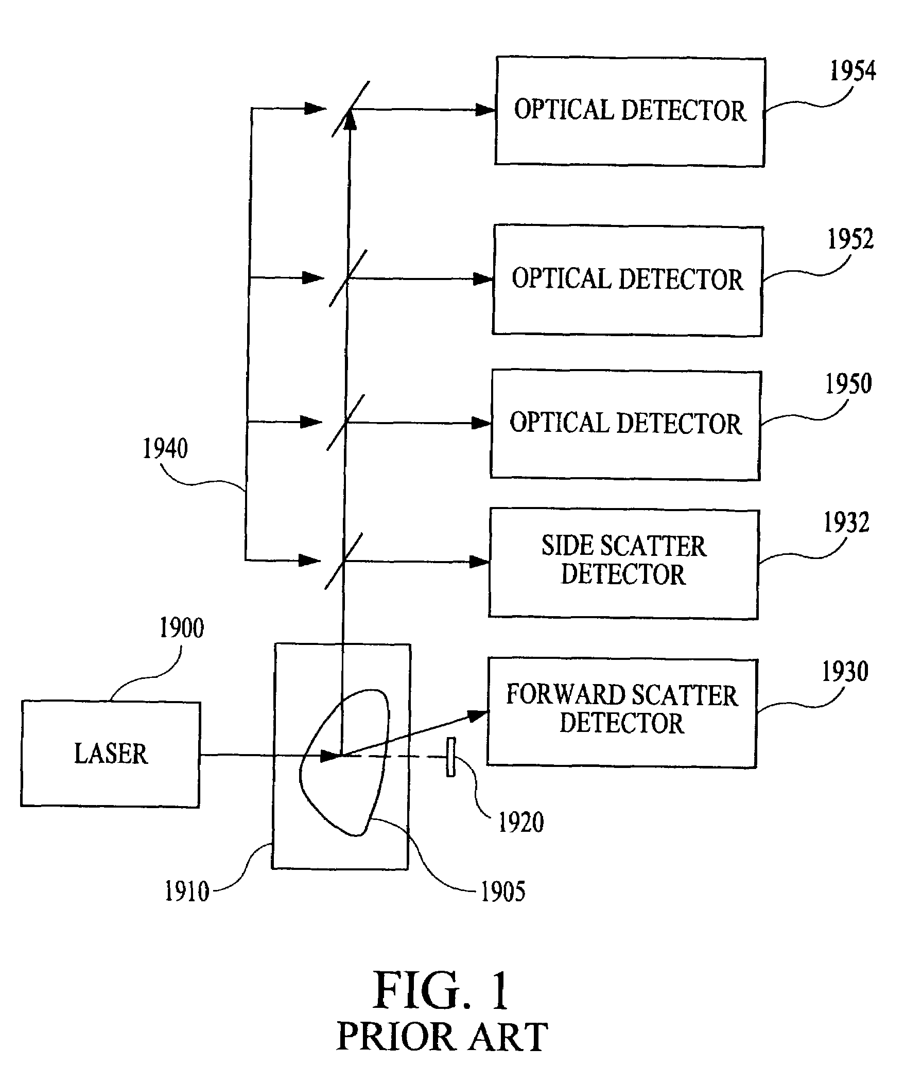
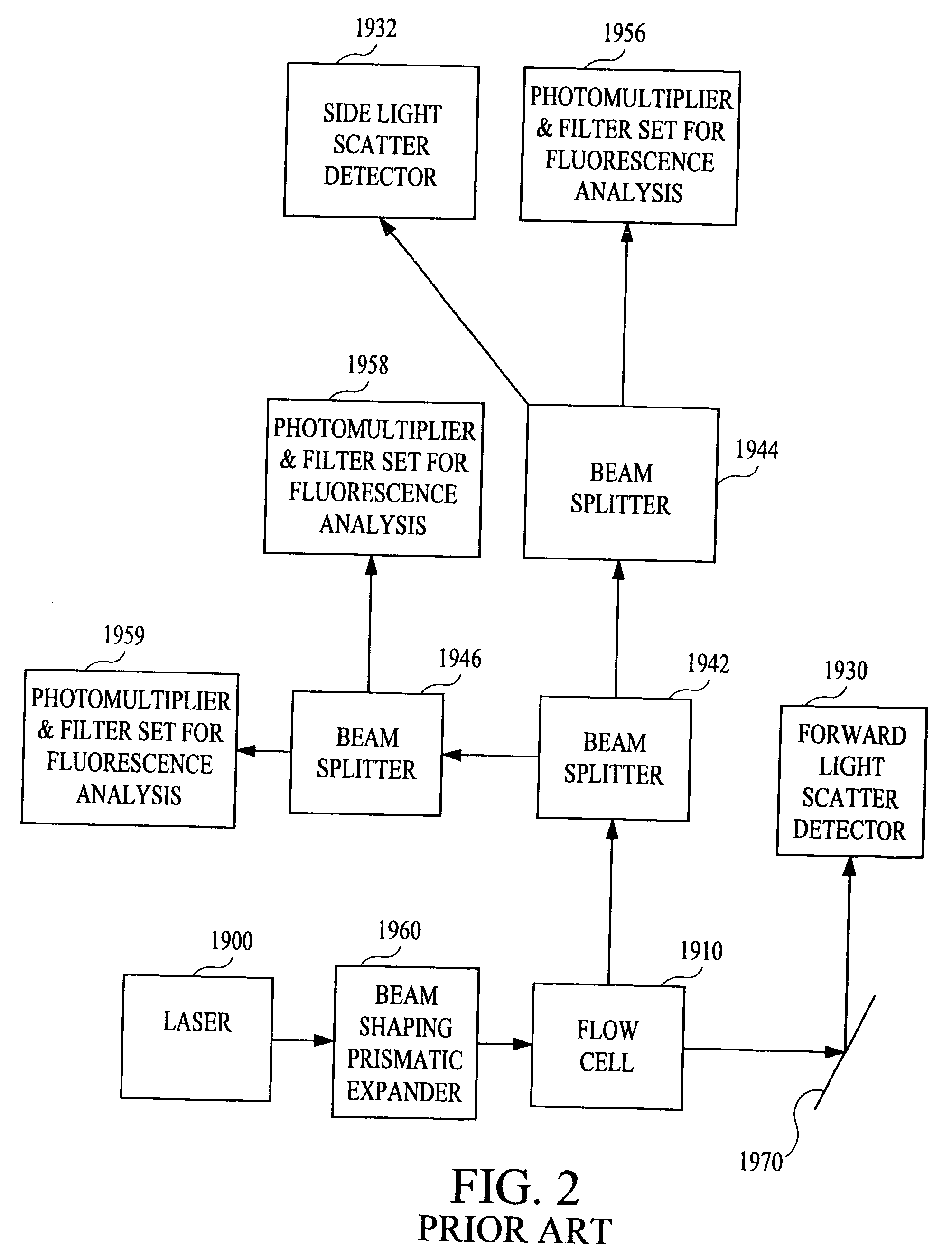
However, I have determined that the properties of the fluorescent dyes themselves limit this flow cytometric technique to about three different wavelengths.
The limitation on the number of fluorescent labels necessarily crimps the amount of analysis that can be done on any one sample.
This necessarily increases the time needed to analyze the sample.
However, time is often not available in an emergency room environment, for example, where a small blood sample must be screened simultaneously for many diagnostic indicators, including therapeutic and abused drugs, hormones, markers of heart attack and inflammation, and markers of hepatic and renal function.
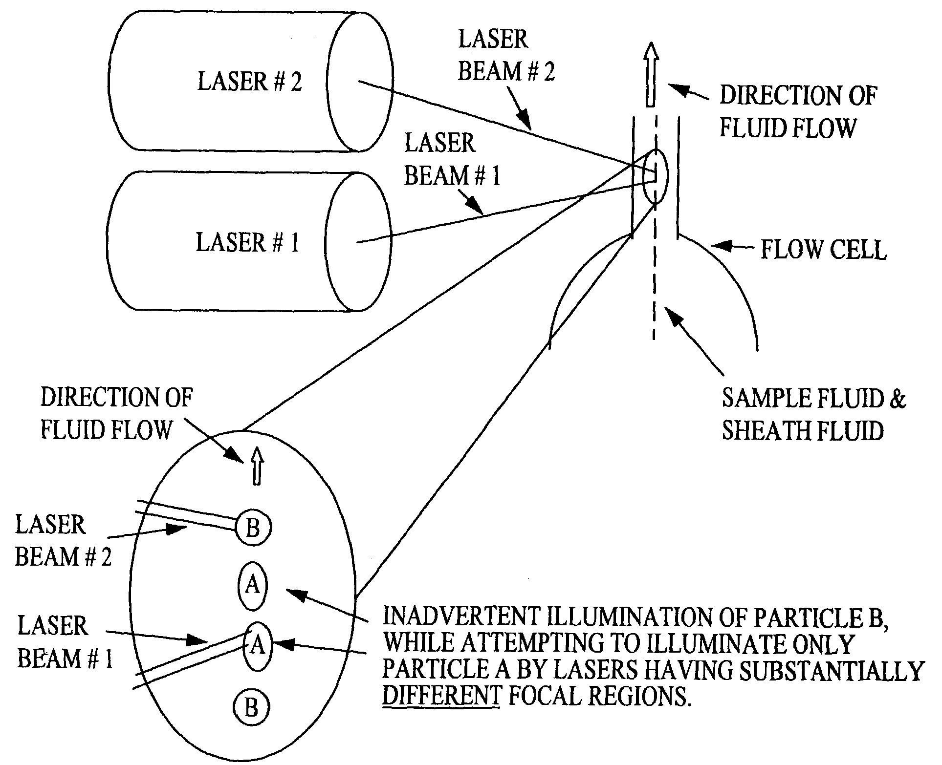
Despite this dual laser approach, I have determined that it is often impossible to know for certain whether the measurements are made on the same particle.
Because the measurement events at the sets of detectors are separated temporally and spatially, I have discovered that, besides laser emission timing problems, even the slightest flow turbulence can mix particles in suspension, thereby increasing the likelihood that subsequent measurements are not made on the same particle as the previous measurements.
As such, it is difficult or impossible to be sure exactly when a particle detected by a detector for Laser #1 will pass through a beam of Laser #2.
Referring to FIG. 3, flow turbulence, for example, causes particle B to change places with particle A such that laser #2 strikes particle B, instead of particle A. By extension, this unacceptable problem compounds as lasers and detectors are added to the device.
Despite this flaw, such multiple illumination beam capabilities have been limited to expensive, complex sorters and are not typically found in smaller, less expensive instruments.
Besides being large and expensive, such machines are often fully burdened in the clinical setting with CD4-CD8 lymphocyte analysis.
Compounding the above-mentioned shortcomings of existing devices and methods, I have discovered that existing methods of data collection and analysis thereof is tedious, slow, and non-real-time.
That is, substantially simultaneous detection of multiple analytes, or of separately identifiable characteristics of one or more analytes, through single-step assay processes is presently not possible, or to the extent possible, has provided limited capability and thus has yielded unsatisfactory results.
First, the length of time typically required to enable detection and classification of multiple analytes is unacceptably long.
Second, the prior art assays exhibited low analyte sensitivities, which often lead to significant analytical errors and unwieldy collection, classification, and analysis of prior art algorithms relative to large amounts of collected data.
In addition to the tedium associated with the above-described bead set separation method, I have discovered that the subjectivity associated with estimating the boundaries of the polygon gates is unacceptable.
It is often impossible to separate some sets of beads because of overlap of bead regions on the FL2-FL3 plot.
Consequently, because of the spill-over, two subsets occupy substantially the same region, making them impossible to distinguish visually there between.
The net result of these difficulties is the inability to determine during a sample run, the existence and quantity of an analyte of interest.
I have also recognized a deficiency in the current approach to signal processing in flow cytometry, which uses peak detectors to measure an event.
Dead time,” the time period during which events can pass through the laser focal point undetected, is highly problematic when the flow cytometer is being used to search for rare events.
Prior art methods, such as U.S. Pat. No. 5,550,058 to Corio et al., incorporated herein by reference, are largely unsuccessful.
However, no known prior art method and / or system, including that of Corio et al., has reduced dead time to zero.
Thus, use of an integrator also fails to reduce dead time to zero.

Method used


Image

  • Multi-analyte diagnostic system and computer implemented process for same
  • Multi-analyte diagnostic system and computer implemented process for same
  • Multi-analyte diagnostic system and computer implemented process for same

Examples


Embodiment Construction

[0144]Generally, the instant multi-analyte diagnostic system performs on a biological sample, bioassays including, for example, immunoassays, complex genetic analyses, and enzymatic assays. To this extent and others U.S. application Ser. No. 08 / 540,814 to Van S. Chandler et al. is incorporated herein by reference in its entirety.

[0145]The biological sample to be tested using the instant invention, for example, includes plasma, serum, tears, mucus, saliva, urine, pleural fluid, spinal fluid, gastric fluid, sweat, semen, vaginal secretion, fluid from ulcers and / or other surface eruptions, blisters, abscesses, and / or extracts of tissues, such as biopsies of normal, malignant, and / or suspect tissues.

[0146]The analytes of interest for these bioassays include, for example, antigens, antibodies, autoantibodies, peptides, proteins, nucleic acid sequences, and / or enzymes. The antigenic analytes, for example, includes bacterial, viral, fungal, mycoplasmal, rickettsial, chlamydial, and / or prot...


PUM

PropertyMeasurementUnit
quantum efficiencyaaaaaaaaaa
sizesaaaaaaaaaa

Abstract

A multi-analyte diagnostic system for use with a computer. The diagnostic system includes a flow analyzer including a co-planar light source-optical detector array, the flow analyzer being communicatable with the computer. The diagnostic system also includes a memory medium readable by the computer and storing computer instructions. The instructions include the following steps. A biological sample is run through the flow analyzer. The identity and quantity of at least one analyte of interest in the biological fluid is determined substantially simultaneously to the sample-running step.

Description

[0001]This application is a continuation of, and claims benefit under 37 U.S.C. § 120 of U.S. patent application Ser. No. 09 / 311,115 filed May 13, 1999 now U.S. Pat. No. 6,592,822, which is incorporated by reference in its entirety, which claims benefit under 37 U.S.C. § 119(e) based on U.S. Provisional Application No. 60 / 085,981, filed May 14, 1998, herein incorporated by reference in its entirety.FIELD OF THE INVENTION[0002]The present invention pertains generally to a diagnostic system and / or method, and more particularly to a substantially simultaneous and multiplexed, multi-analyte diagnostic system and / or method for performing assays using a flow analyzer.BACKGROUND OF THE INVENTION[0003]Flow cytometry utilizes an optical technique that analyzes particles in a fluid mixture based on the particles' optical characteristics using a flow cytometer. Background information on flow cytometry is, for example, found in Shapiro, Practical Flow Cytometry, Third Ed. (Alan R. Liss, Inc. 19...

Claims


Application Information

Patent Timeline
Patent Type & Authority Patents(United States)
IPC IPC(8): G01N21/29G01B5/28G01F1/00G01F17/00G01N21/41G01N15/14G01N21/05G01N21/53G01N21/64G01N33/483
CPCG01N15/1456G01N21/05G01N21/53G01N21/645G01N2015/1477G01N2015/149Y10T436/2575G01N2021/4707G01N2021/4726G01N2021/6441G01N2021/6482G01N2021/0346Y10T436/11G01N2015/1493G01N15/149
Inventor CHANDLER, VAN S.
Owner LUMINEX
Learn More