Eureka AIR delivers breakthrough ideas for toughest innovation challenges, trusted by R&D personnel around the world.

Simulation method and apparatus for use in enterprise controls

a control and simulation method technology, applied in the field of computer systems, can solve the problems of requiring complex control systems, affecting the development process, and requiring tedious steps in the automated manufacturing process, and achieve the effects of facilitating realistic simulation, facilitating modification of circumstantial characteristics, and reducing the number of cas required to support design choices

Inactive Publication Date: 2007-09-04
ROCKWELL AUTOMATION TECH
View PDF26 Cites 85 Cited by
  • Summary
  • Abstract
  • Description
  • Claims
  • Application Information

AI Technical Summary

Benefits of technology

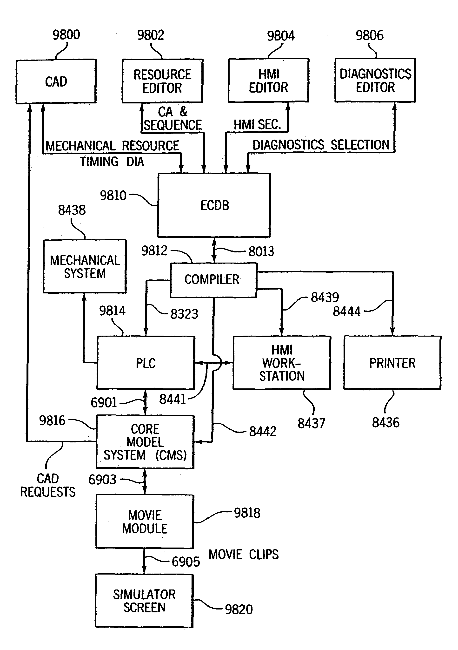
[0065]It has further been recognized that the control engineering phase is a critical juncture for the common threads of information and, that by providing suitable tools to the control engineer which organize the development information, the entire development process can be streamlined and many advantages result. In effect, the inventive tools operate as a lynchpin which enables a control engineer to easily generate controls information from the process information (i.e. specified mechanical tools, behavior and sequencing) and which also enables controls information to be fed back and combined with the process information to virtually simulate a manufacturing process using the actual execution code which will be used in the real world.
[0092]Request events are represented in the CAS and therefore status based diagnostics can easily be provided in each CA to minimize the task of programming diagnostics code for each event in a process. For example, where a clamp CA includes extend and retract requests and ten separate events, diagnostics can be provided once for each event in a template CA and, therefore, as CA instances are instantiated (i.e. selected by an operator for control purposes), the status based diagnostics are proliferated throughout the control process. In this manner, the task of providing status based diagnostics which seemed virtually impossible before can easily be accomplished through CA duplication (i.e., instantiation).

Problems solved by technology

Unfortunately, while automated manufacturing has a large number of advantages, such manufacturing also has a number of shortcomings.
Furthermore, the process engineer specifies resources and goals to drive the manufacturing process and may attempt to generate a cost Justification for the frame assembly manufacturing process.
In most cases many bugs show up during this debugging process and therefore this step in the automated manufacturing process is extremely tedious.
This is particularly true in automated manufacturing which requires complex control systems.
First, the development process is extremely time consuming.
In fact, the typical time required for designing, building, testing and reworking a simple manufacturing line is often months and the time required for a relatively complex line often takes years of man hours.
Second, while some of the development process phases have been streamlined using design software (e.g. CAD and CAM are used to design a door frame assembly and the mechanical tools required to construct the frame assembly), other process phases are not streamlined.
While LL is well suited for controlling industrial processes like those in the automotive industry, LL programming is not an intuitive process and, therefore, requires highly skilled programmers.
Where hundreds of machine tool movements must be precisely synchronized to provide a machining process, programming in LL is extremely time-consuming.
Unfortunately the predefined, fixed logic module approach does not work well for other applications, for example metal-removing applications.
First, there can be considerable variation in how components, such as sensors and actuators, combine to produce even simple mechanisms.
Second, processes like metal removing normally require tightly controlled interaction between many individual mechanisms.
Unfortunately, in reality, there are electrically two types of LSs, one LS type being wired normally opened and the other type wired normally closed.
Alternatively, four unique language modules could be provided, but then the user would have difficulty identifying which of the sixteen physical configurations that the four modules could handle.
Clearly, even for a simple drill mounted on a two position linear slide, application variables make it difficult to provide a workable library of fixed language modules.
Adding more switches to the linear slide only increases, to an unmanageable level, the number of language modules required in the library.
Each tool variable increases the required number of unique LL modules by more than a factor of two, which makes it difficult at best to provide an LL library module for each possible drill configuration.
Taking into account the large number of different yet possible machine-line tools, each tool having its own set of variables, the task of providing an all-encompassing library of fixed language modules becomes impractical.
Even if such a library could be fashioned, the task of choosing the correct module to control a given tool would probably be more difficult than programming the required LL logic from scratch.
For these reasons, although attempts have been made at providing comprehensive libraries of fixed language modules, none has proven particularly successful and much LL programming is done from scratch.
Third, the process of generating schematic control diagrams is extremely labor intensive and thus time consuming.
Nevertheless, these CAD systems can result in erroneous connection specification as a control engineer makes the decisions about how to link control mechanisms.
In this case, the possibility of linking electrical and hydraulic lines incorrectly is exacerbated.
Moreover, in complex control systems, while reducing the overall time required to form a control system schematic, the time is still appreciable.
Fourth, the process of generating diagnostic tools is also not streamlined.
Clearly identifying all interesting conditions and their causes, composing messages for each cause and providing logic to do the same is a complex and time consuming endeavor.
Fifth, the process of specifying HMI design and logic required to support HMI representations is not streamlined.
Sixth, the process of debugging is not streamlined.
Obviously, once tools have been constructed and execution code has been provided the process of backtracking to modify design is difficult and extremely costly.
Once again, line modification is expensive as any system change can ripple through the entire control system thereby requiring additional changes.
While this solution is helpful in visualizing a manufacturing process, unfortunately this solution does not illustrate tool control in the real world which will result from actual execution code.
Unfortunately, while the simulation tools described above are used to drive virtual robots with the actual robot programs which will be used in the real world, similar tools have not been developed for simulating the robot environment (e.g. clamps, sensors, actuators, stops and starts, contingencies, HMIs, etc.).
While these justification system may sometimes fortuitously generate cost data which is close to the actual cost data corresponding to a completed system, in most cases these justification systems provide a ball park figure at best.
Unfortunately, while a ball park figure may be acceptable in some industries, in other industries where competition is particularly keen, such ball park figures are not very helpful in strategic financial planning as even a few percent error may require line redesign.
Thus, it should be appreciated that despite industry efforts to streamline the development process, the development process remains extremely complex.
One important shortcoming is that a system which supports interesting condition or failure reporting typically provides insufficient information to enable a system operator to identify the cause of the failure.
This is because system events may be contingent upon the conclusion of many other events and the diagnostics provided typically cannot indicate which of a long string of contingent events causes a failure or an interesting condition to occur.
While based on experience and hence correct much of the time, these hunches may not be correct and hence may lead an operator in the wrong direction to address the failure this wasting system and operator resources.
For example, while the process engineer can specify specific tools and movements required to carry out a process, the process information is in a form which, while providing specifying information to the control engineer, cannot be used directly by control engineers to perform his development tasks.

Method used


Image

  • Simulation method and apparatus for use in enterprise controls
  • Simulation method and apparatus for use in enterprise controls
  • Simulation method and apparatus for use in enterprise controls

Examples


second embodiment

[0574]According to the inventive simulation aspect, simulation information required for realistic simulation is divided into first and second information sets including “control characteristics” and the combination of both “circumstantial characteristics” and third entity characteristics. Control characteristics are characteristics which, after CA parameterization, are identical for resources corresponding to the CA and are independent of other circumstantial considerations which affect request execution. For example, in the case of a SafeBulkHeadClampSet CA, control characteristics include the devices specified in the CA, resource requests and corresponding I / O combinations and feedback events and corresponding I / O combinations. From a controls perspective all of these characteristics of resources corresponding to a CA are identical.

[0575]Circumstantial characteristics, as the name implies, are characteristics which may vary for a given CA resource and which affect request executio...

first embodiment

[0724]According to the invention, a system and method for developing diagnostic rules for diagnosing the behavior of a machine is provided. The system and method include a plurality of control elements which cooperate to perform at least one discrete event process and which are configured to transition between at least two different states. Each state transition represents a discrete event in the process, and the occurrence of each discrete event is communicated to a main controller. The main controller is configured to detect a timing pattern in the occurrence of the discrete events, which includes a trigger event, a result event, and a time interval between the trigger and result events. A diagnostic rule is then defined based on a statistical analysis of repetitions of the timing pattern. The diagnostic rule is then updated in real time based on a detected change in the timing pattern.

[0725]According to one aspect of the invention, the statistical analysis includes calculating a ...


PUM


Abstract

A method, apparatus and data construct set for generating simulation data structures which can be used by a modeling system to interface between a PLC and simulator, the construct set encapsulating logic and at least a sub-set of simulation information for a particular resource.

Description

CROSS-REFERENCE TO RELATED APPLICATIONS[0001]This is a continuation of U.S. patent application Ser. No. 10 / 304,190 which was filed on Nov. 26, 2002 now U.S. Pat. No. 6,862,553 and is titled “Diagnostics Method and Apparatus For Use With Enterprise Controls” which was a continuation of U.S. patent application Ser. No. 09 / 410,270 which was filed on Sep. 30, 1999 which issued on Apr. 29, 2003 as U.S. pat. No. 6,556,950 and is also titled “Diagnostics Method and Apparatus For Use With Enterprise Controls”.COPYRIGHT NOTIFICATION[0002]Portions of this patent application contain materials that are subject to copyright protection. The copyright owner has no objection to the facsimile reproduction by anyone of the patent document, or the patent disclosure, as it appears in the Patent and Trademark Office.STATEMENT REGARDING FEDERALLY SPONSORED RESEARCH OR DEVELOPMENT[0003]Not applicable.BACKGROUND OF THE INVENTION[0004]This invention generally relates to improvements in computer systems, and...

Claims


Application Information

Patent Timeline
Patent Type & Authority Patents(United States)
IPC IPC(8): G06F11/30G06F15/00G05B23/02
CPCG05B17/02G05B23/0216Y10S707/99943Y10S707/99944
Inventor COBURN, JAMES D.HOSKINS, JOSIAH C.BROOKS, RUVEN E.
Owner ROCKWELL AUTOMATION TECH
Why Eureka
Eureka Blog
Learn More