
Air-conditioning system

Active Publication Date: 2007-09-04
FUTERNIK VLADLEN +1
View PDF22 Cites 23 Cited by
  • Summary
  • Abstract
  • Description
  • Claims
  • Application Information

AI Technical Summary

Benefits of technology

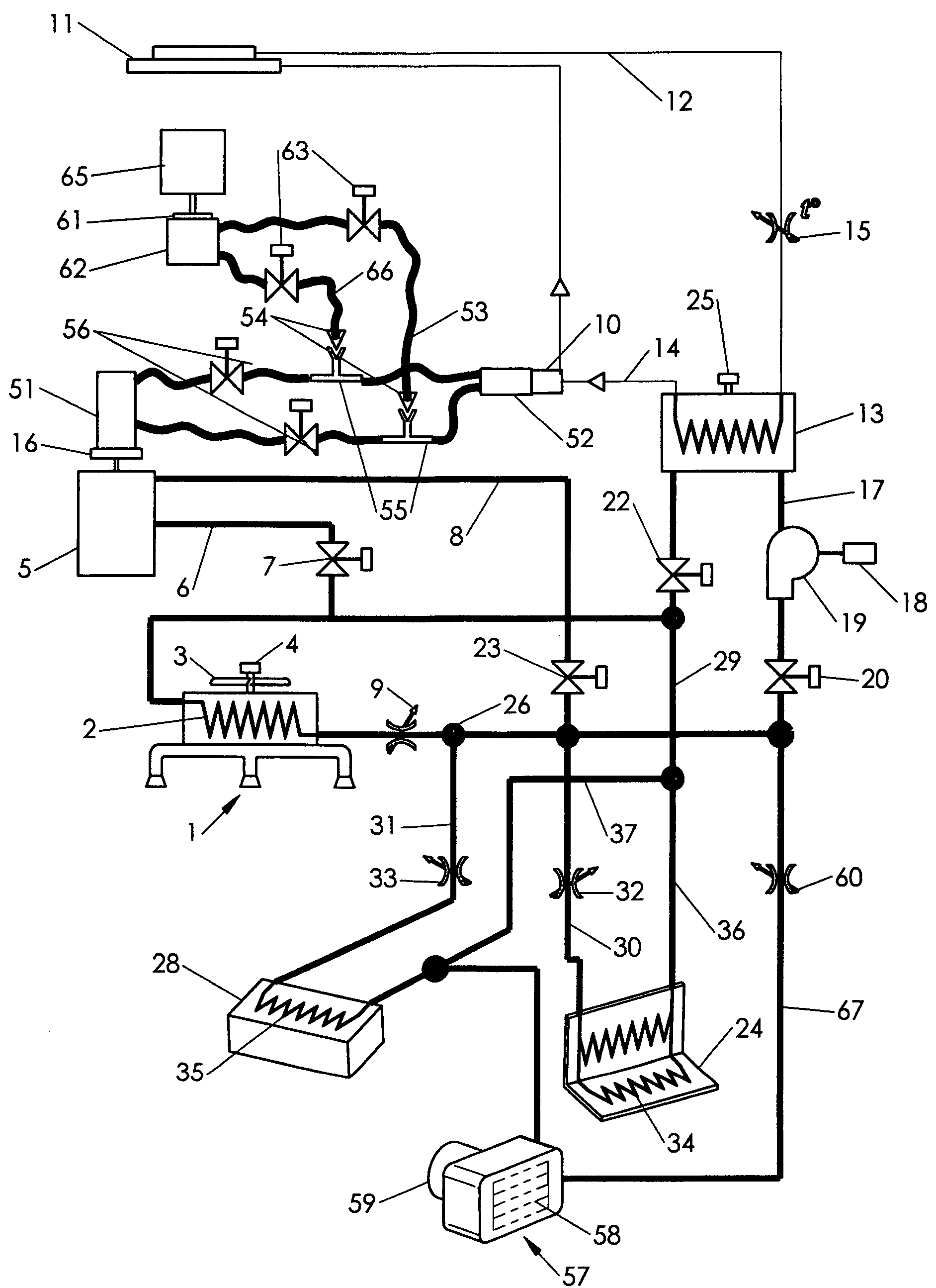
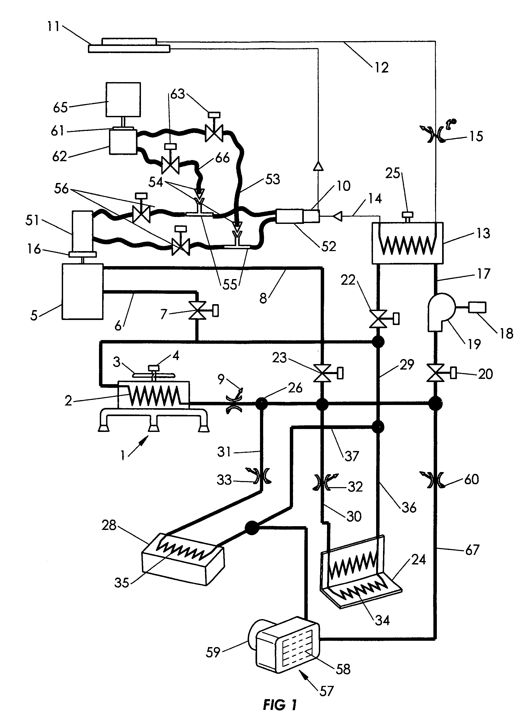
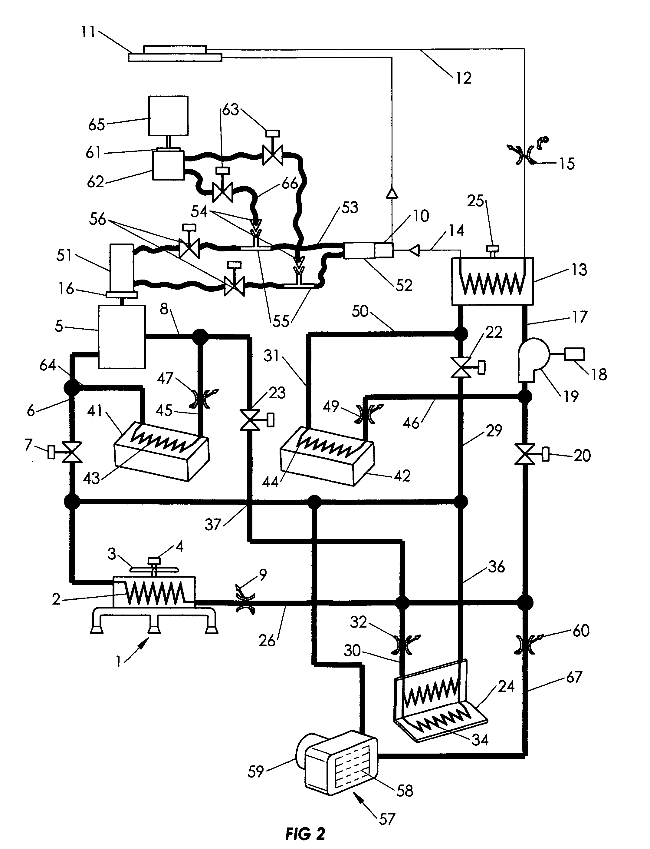
[0010]Similarly to the above-mentioned systems, the heat / cool supplying means of the present system include a hot liquid (heated coolant) contour for circulation of the engine's coolant fed into the at least one heater core to heat the air passed through the heater core (conditioned air); and a refrigerant contour, for circulation of a known refrigerant, fed into a refrigerant / coolant heat exchanger to cool the coolant that may further be used in the aforesaid at least one heater core to cool the air to a required temperature for the vehicle interior.
[0011]Distinctly from the mentioned systems, several important objectives are achieved by this invention. One of them is to provide an extremely economical and efficient vehicle air-conditioning system that can be easily and quickly installed and connected to or removed from the regular engine cooling system, and which is wholly located in the engine compartment or in different conveniently accessible locations of the vehicle.
[0013]The refrigerant contour includes a compressor drawing the refrigerant into a condenser, as in the previous systems. The present system further comprises an oil circulating hydraulic contour, including a hydraulic motor rotating the compressor, which motor is operated preferably by oil under pressure delivered through a flexible hose from an oil hydraulic pump driven by the main vehicle engine and / or a less powerful substitute engine connected by an electromagnetic clutch to the compressor. Thus, when the vehicle is parked, the air-conditioning system may still be on and more efficiently operate using the substitute engine, saving fuel, and reducing pollution.

Problems solved by technology

Yet, those system are not highly efficient at least for two reasons: a) the vehicle's main engine has to run all the time to provide power for the refrigerant contour, or heat for the coolant contour, which causes significant loss of energy and high level of pollution (e.g. when a bus driver is waiting for passengers while there are no passengers in the bus); b) the produced heat or cool air provides all passengers of the vehicle with the same air temperature, though different spots of each passenger's body may require different temperatures (e.g. the front of one passenger's body needs less cool air, but the back is sweating and requires more cool air, whereas another passenger does not need the conditioned air at all), and some regions of the vehicle's interior may not require the conditioned air (e.g. when the respective seats are empty).

Method used


Image

  • Air-conditioning system
  • Air-conditioning system
  • Air-conditioning system

Examples


Embodiment Construction

[0026]While the invention may be susceptible to embodiment in different forms, there are shown in the drawings, and will be described in detail herein, specific embodiments of the present invention, with the understanding that the present disclosure is to be considered an exemplification of the principles of the invention, and is not intended to limit the invention to that as illustrated and described herein.

[0027]A preferred embodiment of the inventive device (air-conditioning system), illustrated on FIG. 1, for temperature control in a vehicle comprises a control system including conventional elements and programmed instructions (not illustrated); and at least two circulation contours: a refrigerant circulating contour (depicted on FIG. 1 by a thin line), and a coolant circulating contour (depicted on FIG. 1 by a bold line). The coolant contour includes an air outlet unit (1), provided with several outlets. A known heater core (2) is located before the inlets inside of the unit 1....


PUM


Abstract

An air-conditioning system embodiment for temperature control in a vehicle comprises heater cores, controllably connected to a coolant contour, outletting the conditioned air towards a person sitting in a chair, or into a food compartment. Some cores are mounted inside of chairs' backs situated in front of rear passengers, other cores are mounted in the chair back and inside the chair seat. A refrigerant-coolant heat exchanger provides heat exchange between a refrigerant contour and the coolant contour, cooling the coolant supplied to the cores. A refrigerant compressor is driven by a hydraulic motor, operated by pressurized oil delivered through a hydraulic contour from a first hydraulic pump driven by the vehicle's engine connected to the first pump through an electromagnetic clutch, or alternatively from a second hydraulic pump driven by a substitute engine, connected to the second pump through another electromagnetic clutch, both clutches are controlled by a thermostat.

Description

FIELD OF THE INVENTION[0001]The invention relates to air conditioner systems, particularly, but not exclusively to air-conditioning systems intended for vehicles, which vehicles can be initially designed with an air conditioner, or initially designed without an air conditioner but having only a liquid cooling system for the engine.BACKGROUND OF THE INVENTION[0002]There exists a wide variety of air conditioners employed at premises and inside transportation means. The proposed inventive system though substantially differs from the known devices in several aspects indicated further below.[0003]A patent U.S. Pat. No. 6,793,016 teaches an air-conditioning unit for blowing air into a passenger's compartment and cooling a vehicle's seat. The present inventive system, in contrast, provides the cooling and heating of the blown air by means of a heat exchanger wherein the blown air is heated or cooled by hot or cold coolant liquid generally used for cooling the vehicle's engine.[0004]A syste...

Claims


Application Information

Patent Timeline
IPC IPC(8): F25B29/00B60H1/00B60H3/00
CPCB60H1/00435
Inventor FUTERNIK, VLADLENFUTERNIK, BORIS
Owner FUTERNIK VLADLEN
Learn More