
Video and graphics system with MPEG specific data transfer commands

a video and graphics system and data transfer technology, applied in the field of integrated circuit systems, can solve problems such as memory transfer inefficiencies

Inactive Publication Date: 2007-08-14
QUALCOMM INC
View PDF336 Cites 56 Cited by
  • Summary
  • Abstract
  • Description
  • Claims
  • Application Information

AI Technical Summary

Benefits of technology

[0006]One embodiment of the present invention is a method of accessing a memory for processing compressed video data including: requesting to transfer the compressed video data using one of a plurality of addressing patterns, reading the compressed video data from the memory using the addressing pattern if a read operation has been requested, and writing the compressed video data to the memory using the addressing pattern if a write operation has been requested. The compressed video data may include MPEG-2 video data containing HDTV data or SDTV data, and the addressing patterns may include predetermined addressing patterns as well as programmable addressing patterns. The use of the predetermined addressing patterns results in receiving the compressed video data in a predetermined order in a less number of clock cycles.

Problems solved by technology

During decoding of MPEG-2 video data in conventional systems, memory transfer inefficiencies exist because conventional memory organization and addressing schemes do not take into account memory access requirements for MPEG-2 video decoding.

Method used


Image

  • Video and graphics system with MPEG specific data transfer commands
  • Video and graphics system with MPEG specific data transfer commands
  • Video and graphics system with MPEG specific data transfer commands

Examples


Embodiment Construction

I. Graphics Display System Architecture

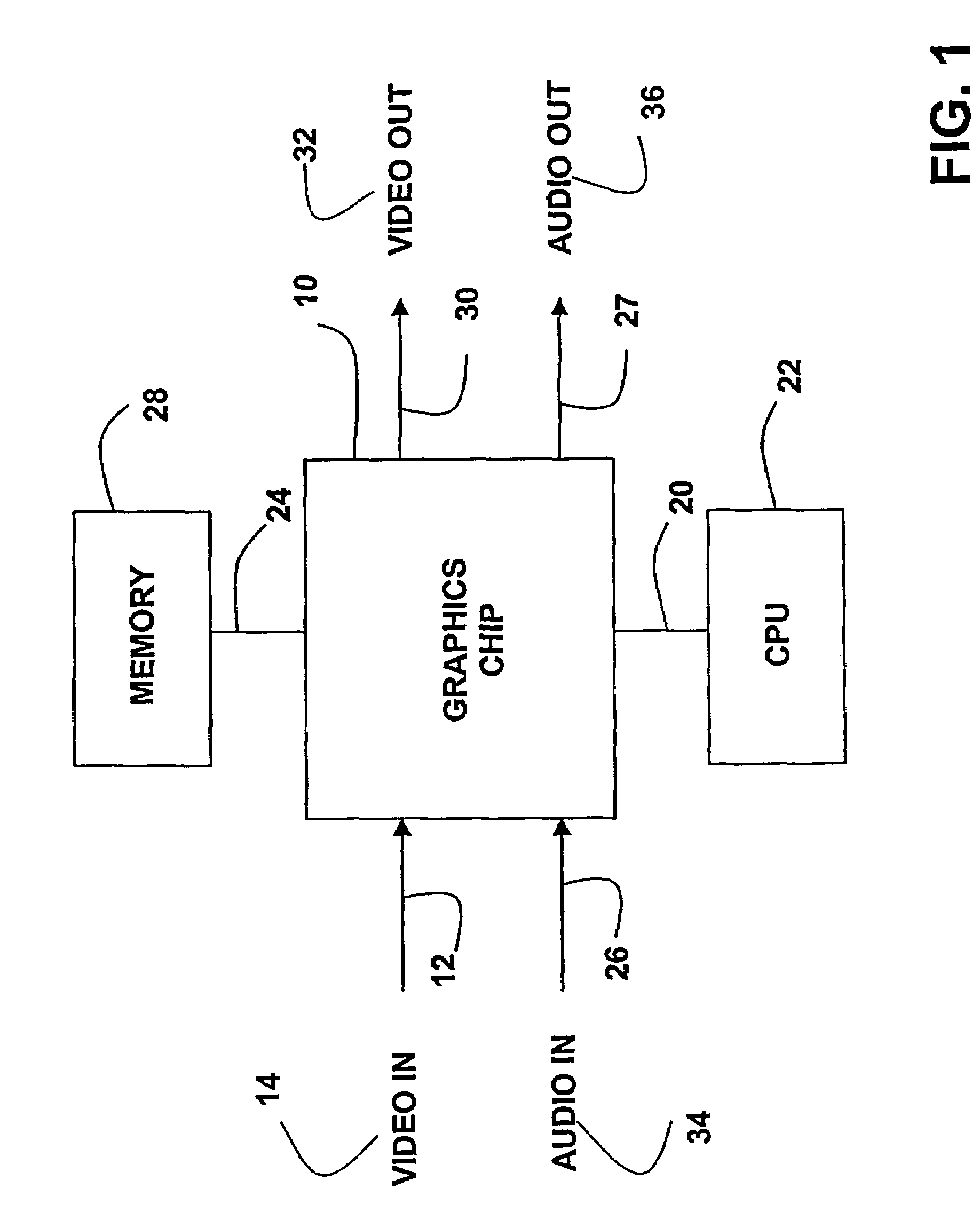
[0083]Referring to FIG. 1, the graphics display system according to the present invention is preferably contained in an integrated circuit 10. The integrated circuit may include inputs 12 for receiving video signals 14, a bus 20 for connecting to a CPU 22, a bus 24 for transferring data to and from memory 28, and an output 30 for providing a video output signal 32. The system may further include an input 26 for receiving audio input 34 and an output 27 for providing audio output 36.

[0084]The graphic display system accepts video input signals that may include analog video signals, digital video signals, or both. The analog signals may be, for example, NTSC, PAL and SECAM signals or any other conventional type of analog signal. The digital signals may be in the form of decoded MPEG signals or other format of digital video. In an alternate embodiment, the system includes an on-chip decoder for decoding the MPEG or other digital video signals input...


PUM


Abstract

A video and graphics system includes a video decoding system for processing compressed video data. The compressed video data includes MPEG-2 video data containing SDTV video data or HDTV video data. The video decoding system includes a video decoder for processing the compressed video data to generate displayable video, and a memory controller for transferring the compressed video data to and from an external memory. The video decoder requests to the memory controller to transfer the compressed video data using one of predetermined addressing patterns. The predetermined addressing patterns allow for more efficient transferring of the compressed video data to and from the external memory when compared to sequentially transferring a fixed number of data bytes starting at a fixed address. The use of the predetermined addressing patterns results in reading the compressed video data from the external memory in a predetermined order in a less number of clock cycles. The use of the predetermined addressing patterns also results in transferring the compressed video data over the data bus between the memory controller and the video decoder in a less number of clock cycles.

Description

CROSS-REFERENCE TO RELATED APPLICATION(S)[0001]This application is a continuation of U.S. patent application Ser. No. 09 / 643,223, filed Aug. 18, 2000 now U.S. Pat. No. 6,661,422, which is a continuation-in-part of U.S. patent application Ser. No. 09 / 437,208, filed Nov. 9, 1999, now U.S. Pat. No. 6,570,579, issued on May 27, 2003 and entitled “Graphics Display System,” which claims the benefit of the file date of U.S. provisional patent application No. 60 / 107,875, filed Nov. 9, 1998, and claims the benefit of the filing date of U.S. provisional patent application No. 60 / 170,866, filed Dec. 14, 1999 and entitled “Graphics Chip Architecture,” the contents of which are hereby incorporated by reference.[0002]The present application contains subject matter related to the subject matter disclosed in U.S. patent application Ser. No. 09 / 641,374 entitled “Video, Audio and Graphics Decode, Composite and Display System,” U.S. patent application Ser. No. 09 / 641,936 entitled “Video and Graphics S...

Claims


Application Information

Patent Timeline
IPC IPC(8): H04N9/64G06F12/00G06T1/60G09G5/36G11C8/00G06F12/02G06F15/167G06T9/00G09G1/16G09G5/00G09G5/02G09G5/06G09G5/12G09G5/14G09G5/28G09G5/34G09G5/39G09G5/395G09G5/397G09G5/42H04N5/14H04N5/44H04N5/445H04N5/45H04N5/46H04N7/01H04N9/45H04N11/14H04N11/20
CPCG06T9/007H04N19/436G09G5/06G09G5/12G09G5/14G09G5/28G09G5/346G09G5/36H04N5/14H04N5/44504H04N5/44508H04N5/44591H04N5/45H04N7/0135H04N9/45H04N9/641H04N9/642H04N21/42204H04N21/42653H04N21/4305H04N21/4316H04N21/434H04N21/4438H04N21/47H04N19/61H04N19/44H04N19/42H04N19/423G09G5/001G09G5/02G09G5/024G09G5/026G09G2310/0224G09G2320/0247G09G2340/02G09G2340/0407G09G2340/10G09G2340/125G09G2360/02G09G2360/121G09G2360/125G09G2360/128H04N5/126H04N5/4401H04N5/46H04N11/143H04N11/20G06T1/60H04N21/426
Inventor VALMIKI, RAMANUJAN K.KUMAR, SATHISH
Owner QUALCOMM INC
Learn More