Thermal optimization of EMI countermeasures

Inactive Publication Date: 2007-07-31
ROBERT BOSCH CORP
View PDF29 Cites 2 Cited by
  • Summary
  • Abstract
  • Description
  • Claims
  • Application Information

AI Technical Summary

Benefits of technology

[0005]Accordingly, there is a need for improved EMI countermeasures, particularly countermeasures that perform in environments where excess heat can be problematic. The present invention provides an electronic circuit and EMI countermeasure for an automotive electronic control unit that provides a maximum amount of EMC protection under normal operating conditions, i.e., a range of typically encountered ambient temperatures. The effectiveness of the EMI countermeasure is reduced at extremely high temperatures. The electronic circuit and EMI countermeasure enhance the effectiveness of EMI countermeasures as a function of temperature to improve performance under normal conditions. This feature allows for a less-expensive housing to be used for an electronic control unit in which the electronic circuit (such as a control circuit) and EMI countermeasure are placed.
[0006]In one embodiment, the invention includes a method of controlling a device or module (generically referred to as an actuator). The method includes the acts of providing a control signal to an input circuit of a switch, the input circuit including a filter, the control signal having a plurality of peaks and a plurality of troughs and a plurality of edges, each edge running from one of the peaks to one of the troughs or one of the troughs to one of the peaks, controlling the speed of the plurality of edges by processing the control signal in the filter, the filter operable to maintain the speed of the edges at a relatively low value or rate in an ambient temperature range and to increase the speed of the edges at temperatures that are higher than the ambient temperature range, and providing the processed control signal to the switch.

Problems solved by technology

One weakness of electronic devices is their susceptibility to performance degradation when subjected to electromagnetic interference (“EMI”).
Most, if not all, electronic devices are susceptible to EMI from one source or another under the right conditions.
As noted, EMI countermeasures may cause excessive heat.
If the circuits are subjected to conditions beyond their limits, they will malfunction.
In addition to heat caused by the operation of electronic and electric devices, the environmental temperature and other heat sources may combine to cause malfunctioning of electronic components and electronic circuits.

Method used


Image

  • Thermal optimization of EMI countermeasures
  • Thermal optimization of EMI countermeasures
  • Thermal optimization of EMI countermeasures

Examples


Embodiment Construction

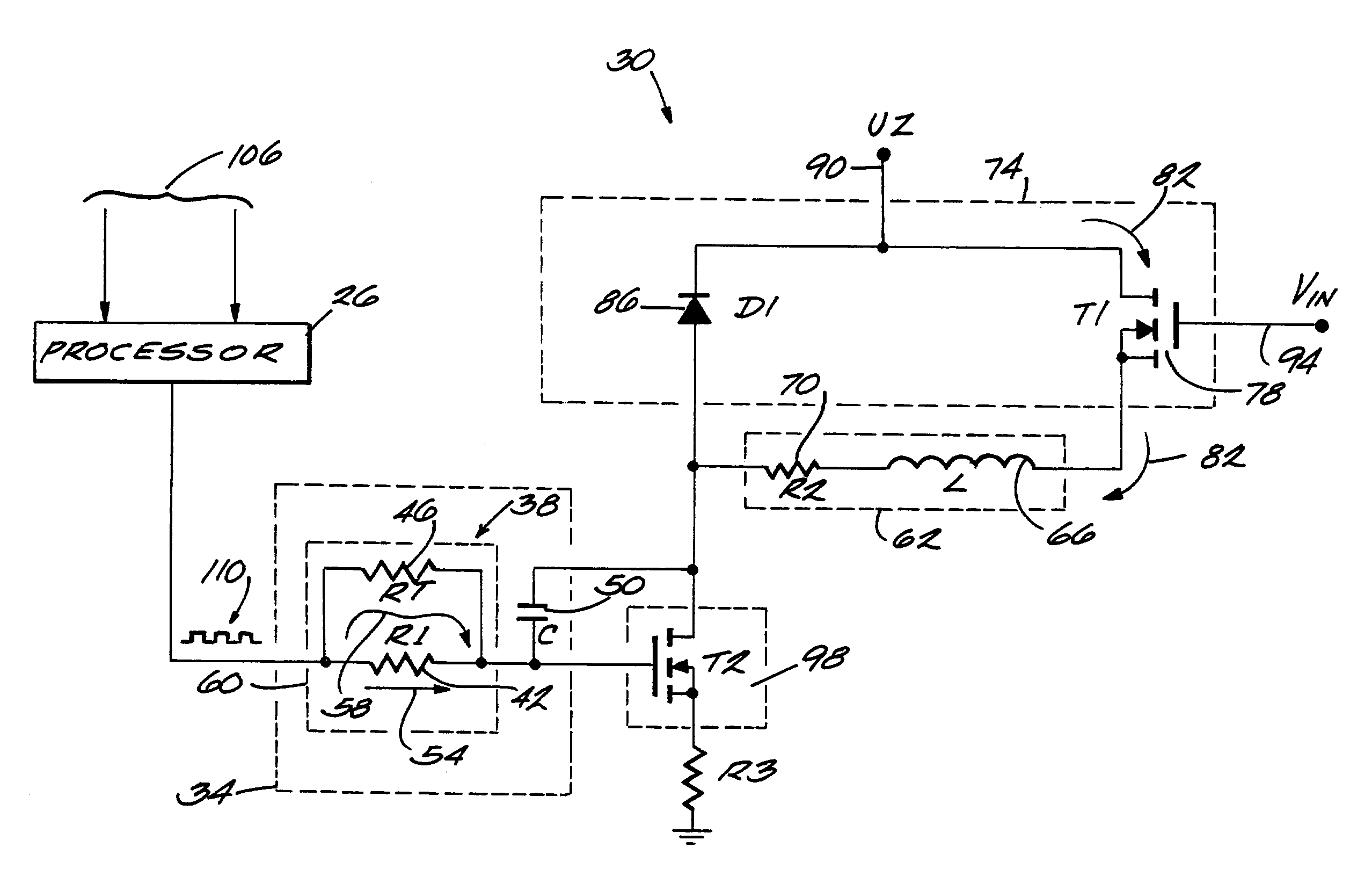
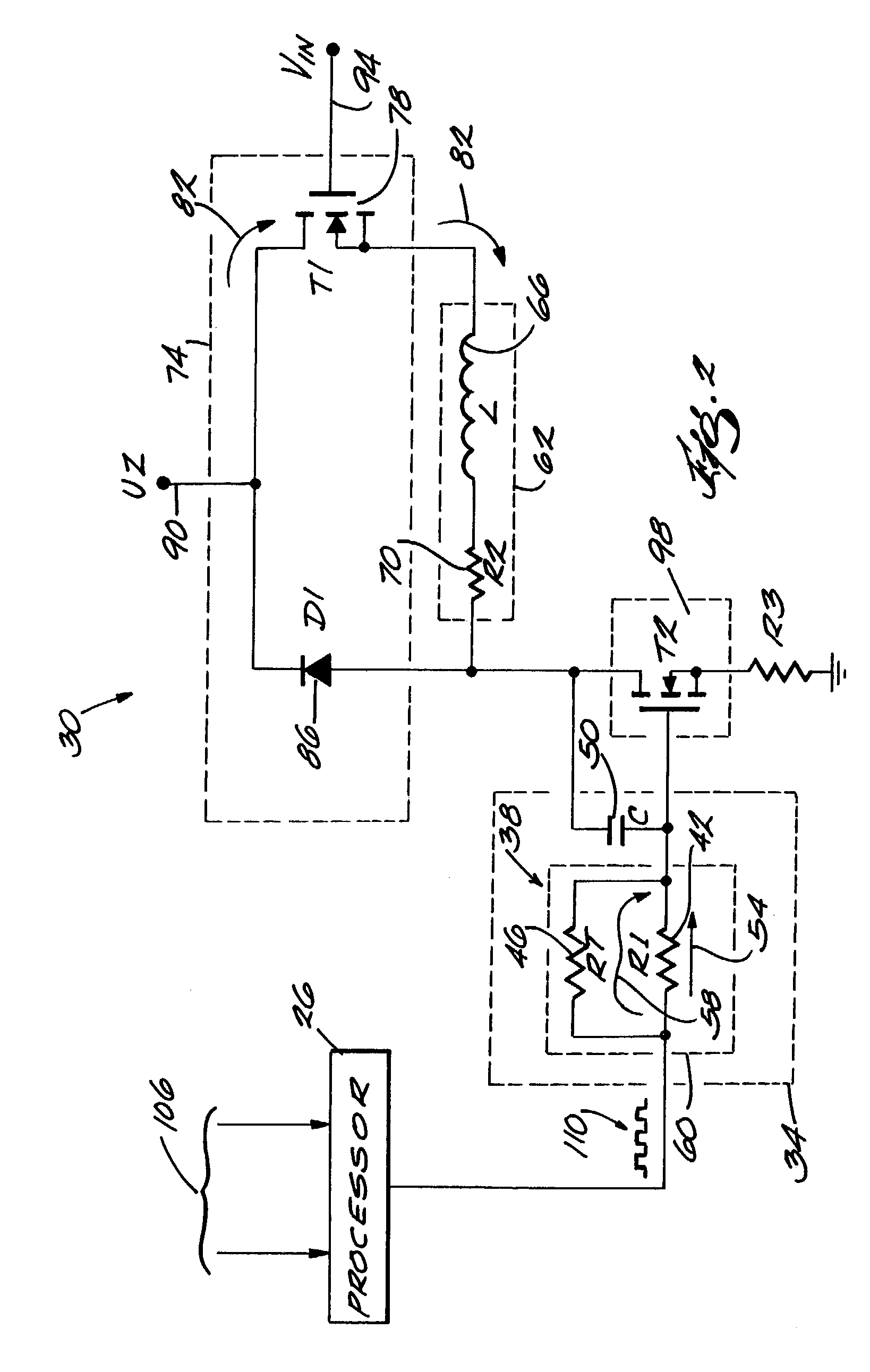
[0014]Before embodiments of the invention are explained in detail, it is to be understood that the invention is not limited in its application to the details of the examples set forth in the following description or illustrated in the drawings. The invention is capable of other embodiments and of being practiced or carried out in a variety of applications and in various ways. Also, it is to be understood that the phraseology and terminology used herein is for the purpose of description and should not be regarded as limiting. The use of “including,”“comprising,” or “having” and variations thereof herein is meant to encompass the items listed thereafter and equivalents thereof as well as detector, or a crystal. The resistor 42 is positioned in path 54. The temperature-dependent resistor 46 is in a parallel path 58 with respect to the resistor 42. The resistor 42 and temperature-dependent resistor 46 form a network 60. In one embodiment, the resistor 42 has a value of 1 KΩ, the tempera...


PUM


Abstract

The present invention provides an electronic circuit and EMI countermeasure for an automotive electronic control unit that provides a maximum amount of EMI protection under normal operating conditions, i.e., ambient temperatures. The effectiveness of the EMI countermeasure is limited at extremely high temperatures. The electronic circuit and EMI countermeasure optimizes the effectiveness of EMI countermeasures as a function of temperature to improve performance under normal conditions.

Description

FIELD OF THE INVENTION[0001]The invention generally relates to methods and systems for ensuring electromagnetic compatibility (“EMC”) in automotive systems. More specifically, the invention relates to adjusting the operation of EMC devices and EMI countermeasures to account for or otherwise take into consideration temperature and thermal effects.BACKGROUND OF THE INVENTION[0002]The reliability, low cost, and ability to provide control over a wide variety of devices, systems, and processes has made electronic circuits and devices ubiquitous. However, like any other technology, electronic devices are designed as a trade-off among mutually exclusive constraints. One weakness of electronic devices is their susceptibility to performance degradation when subjected to electromagnetic interference (“EMI”). EMI is produced by a variety of sources (e.g., transformers, stray radio signals, motors, heat, and other machines and sources that generate electric or magnetic fields.) Most, if not all...

Claims


Application Information

Patent Timeline
IPC IPC(8): G06F7/00F02P19/00B60T8/173B60W50/00B62D5/04G06F19/00
CPCB60T8/173B62D5/0457B62D5/0496B60W2050/0052B60W2050/0059B60W2550/12B60W2555/20
Inventor KASTER, ROBERT
Owner ROBERT BOSCH CORP
Why Eureka
Try Eureka