Three-dimension imaging lidar

a three-dimensional imaging and lidar technology, applied in the field of optical scanning system, can solve the problems of unqualified engineering and scientific success, inability to generate and the first-generation altimetric approach is not well-suited to generating the few meter-level horizontal resolution and decimeter

Active Publication Date: 2007-07-24
UNITED STATES OF AMERICA AS REPRESENTED BY THE ADMINISTATOR OF THE NAT AERONAUTICS SPACE ADMINISTATION
View PDF8 Cites 185 Cited by
  • Summary
  • Abstract
  • Description
  • Claims
  • Application Information

AI Technical Summary

Problems solved by technology

Nevertheless, MOLA provided the most accurate global vertical height datum ever achieved from planetary orbit and was an unqualified engineering and scientific success.
First generation altimetric approaches are not well-suited to generating the few meter level horizontal resolution and decimeter precision vertical (range) resolution on the global scale desired by many in the Earth and planetary science communities.
On Earth, the presence of manmade buildings and volumetric scatterers (such as tree canopies or other vegetation) generally makes waveform interpretation more complex and difficult.
Clearly, one major challenge to the conventional approach is the sheer number of measurements required over a nominal mission lifetime of two to three years.
If one were to simply scale conventional approaches, one would clearly face severe prime power, weight, and instrument longevity issues.
A second technical challenge is the high ground speed of the spacecraft (about 3 km / sec for a nominal 300 km altitude Mars orbit) coupled with the need to incorporate a scanner to cover the large area between adjacent ground tracks, especially near the equator.
While alternative non-mechanical scanners, such as electro-optic or acousto-optic devices, are capable of very high scanning speeds and have no moving parts, they fall far short of the angular range requirements, are highly limited in their useful aperture, and require fast high voltage or high RF power drivers.
An additional technical challenge stems from the high laser fire rate and the long pulse time of flight (TOF).
While such a navigation accuracy might be easy to achieve in Earth orbit using either Global Positioning System (GPS) receivers or Satellite Laser Ranging (SLR) to passive reflectors on the spacecraft, it would likely be a much more difficult challenge in orbits about extraterrestrial bodies.
A second technical problem associated with the longer pulse TOF from orbit is related to “transmitter point-ahead”, i.e. the offset between the center of the laser beam at the surface and where the receiver is looking one 2 msec round trip transit time later.
This approach greatly increases the solar background noise incident on the detector during local daytime operations relative to the unscanned case and elevates the laser output energy requirements for good discrimination of the signal.

Method used


Image

  • Three-dimension imaging lidar
  • Three-dimension imaging lidar
  • Three-dimension imaging lidar

Examples


Embodiment Construction

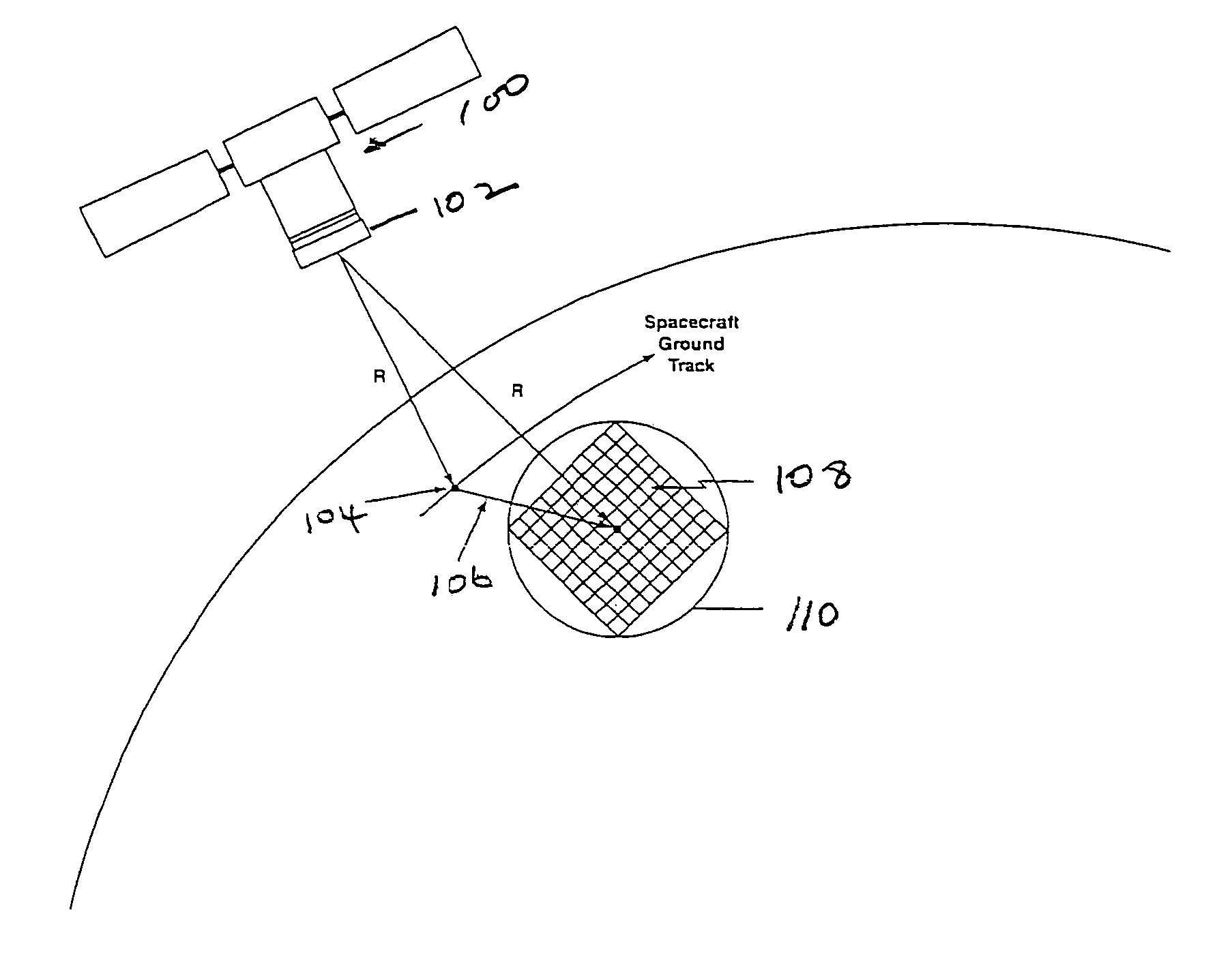
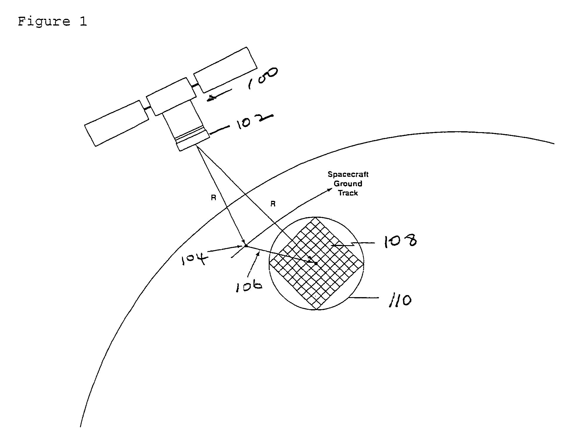
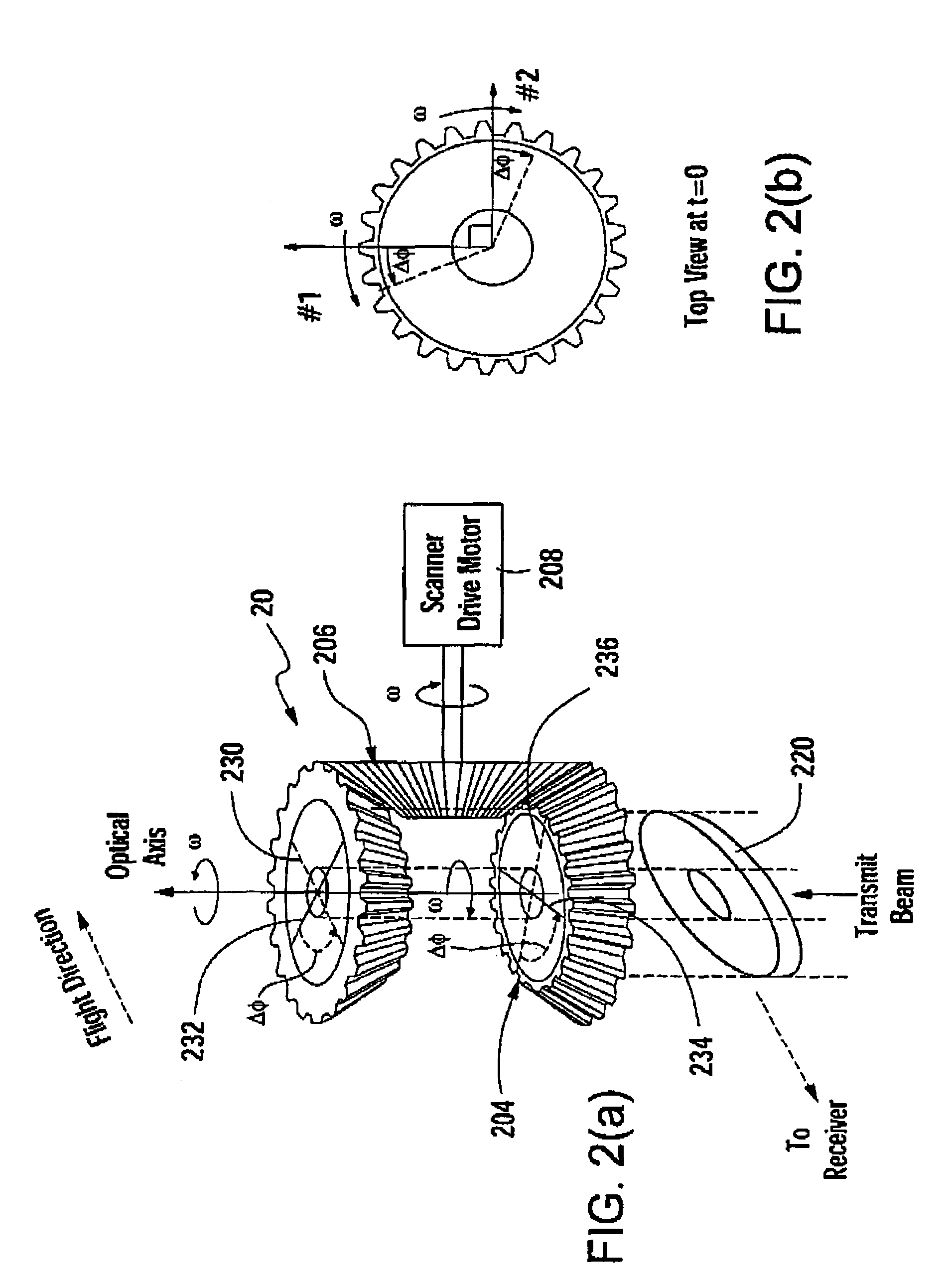
[0025]This invention is directed to an optical scanning system for transmitting and receiving light beams. A three dimension (3-D) imaging lidar overcomes major technological impediments to achieving few meter transverse resolutions. The 3-D imaging lidar includes modest power kHz rate lasers, array detectors, photon-counting multi-channel timing receivers, and dual wedge optical scanners.

Array Detectors

[0026]The unrealistically high laser fire rates and scan rates previously described above can only be ameliorated by making many spatially resolved measurements within a single pulse. This can be accomplished by replacing the single element detector with a highly pixellated array detector. The ground scene is then imaged by the receiver telescope onto the array such that each pixel records the laser photon returns from a single 5 m×5 m resolution element on the planetary surface (along with noise) and inputs them into a separate timing channel. Of course, one must now provide a multi...


PUM


Abstract

This invention is directed to a 3-dimensional imaging lidar, which utilizes modest power kHz rate lasers, array detectors, photon-counting multi-channel timing receivers, and dual wedge optical scanners with transmitter point-ahead correction to provide contiguous high spatial resolution mapping of surface features including ground, water, man-made objects, vegetation and submerged surfaces from an aircraft or a spacecraft.

Description

CROSS-REFERENCES TO RELATED APPLICATIONS[0001]This application now formalizes and incorporates herein by reference Provisional Application Ser. No. 60 / 448,602, “SPACEBORNE 3D IMAGING LIDAR,” John J. Degnan, filed on Feb. 14, 2003. Applicant claims the priority date thereof under 35 U.S.C. 119(e).ORIGIN OF THE INVENTION[0002]The invention described herein was made by an employee of the United States Government. Therefore, the invention may be manufactured and used by or for the Government for governmental purposes without the payment of any royalties thereon or therefor.FIELD OF THE INVENTION[0003]The invention relates to an optical scanning system and more particularly to a three-dimension imaging lidar.BACKGROUND ART OF THE INVENTION[0004]Over the past two decades, there has been an increasing interest in, and proliferation of, airborne laser altimeters, which measure the roundtrip time of flight of a laser pulse from an aircraft to a surface. High speed optical scanning devices of...

Claims


Application Information

Patent Timeline
Patent Type & Authority Patents(United States)
IPC IPC(8): G01C3/08
CPCG01C3/08G01C7/00G01S7/4811G01S7/4813G01S7/4817G01S17/89G02B26/105
Inventor DEGNAN, JOHN J.
Owner UNITED STATES OF AMERICA AS REPRESENTED BY THE ADMINISTATOR OF THE NAT AERONAUTICS SPACE ADMINISTATION
Why Eureka
Try Eureka