Inhalers
a technology of inhaler and air, which is applied in the field of inhalers, can solve the problems of difficult provision of inhalable aerosol, and achieve the effects of reducing the amount of deposition, and increasing the effective viscosity of the air
- Summary
- Abstract
- Description
- Claims
- Application Information
AI Technical Summary
Benefits of technology
Problems solved by technology
Method used
Image
Examples
first embodiment
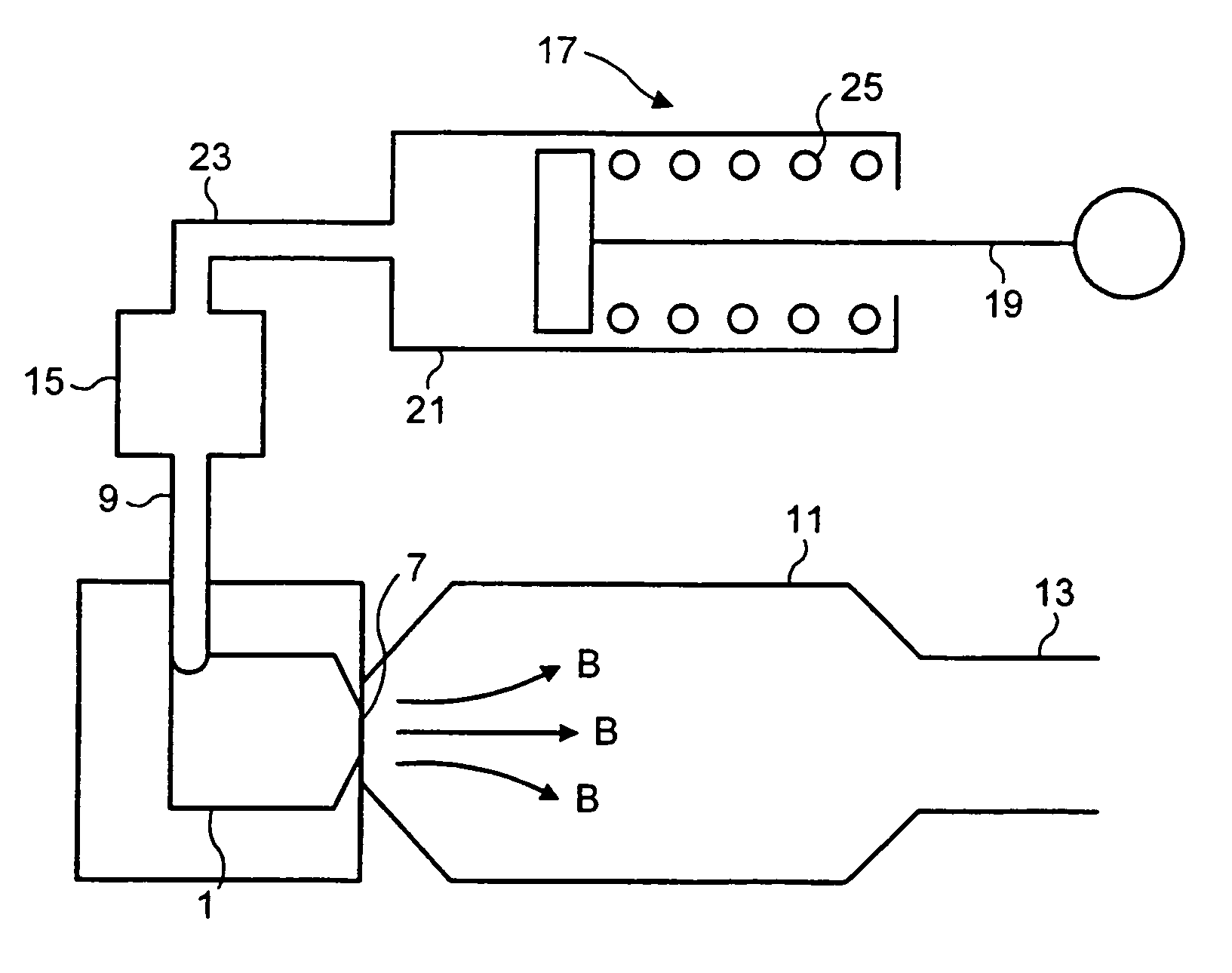
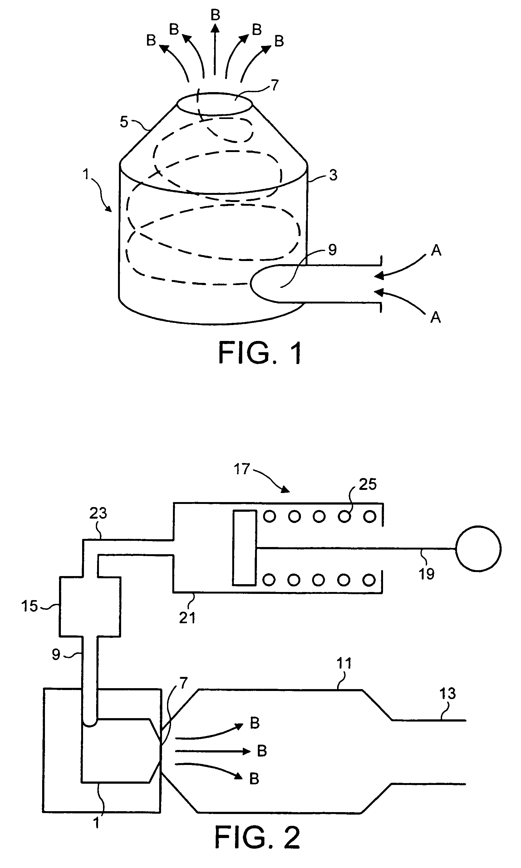
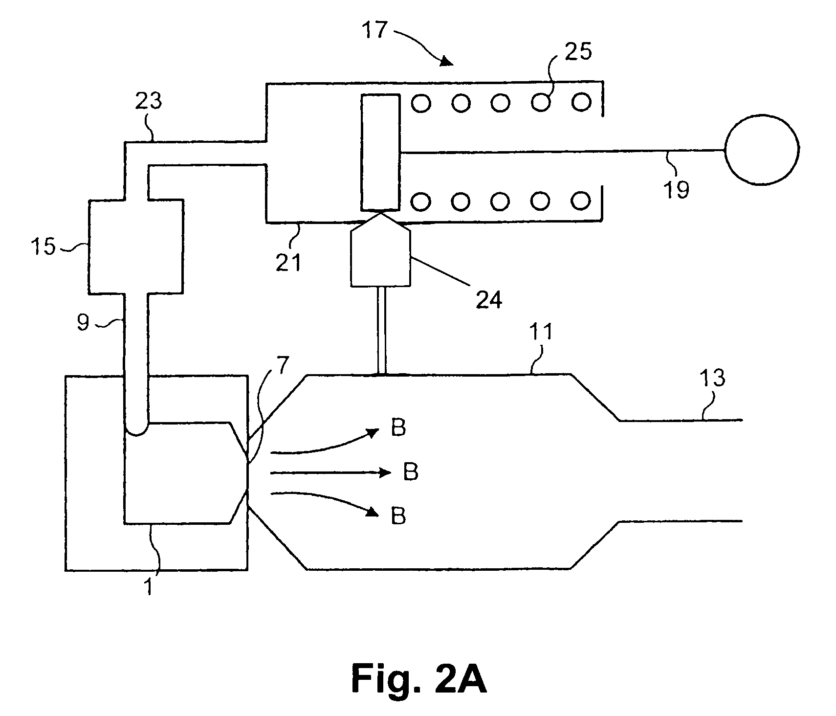
[0046]FIG. 2 shows the invention. According to this embodiment a cyclone 1 is connected to a chamber 11 having a mouthpiece 13. The chamber has a volume of around 300 ml. The cyclone 1 is located at an end of the chamber 11 opposite the mouthpiece 13, and the outlet 7 of the cyclone 1 is arranged to eject the aerosol of medicament into the chamber 11 towards the mouthpiece 13, as indicated by arrows B.
[0047]A drug dosing device 15 is connected to the inlet 9 of the cyclone 1 and is arranged such that, as a flow of air passes through the dosing device 15, a controlled dose of medicament is entrained in the airflow.
[0048]The airflow to the drug dosing device 15 is provided by a pump 17, which comprises a plunger 19 received in a pump cylinder 21 and biased towards an outlet 23 of the pump 17 by a spring 25. A breath-actuated mechanism 24 is used to retain the plunger 19 in a retracted position against the biasing force of the spring 25 until the medicament is to be delivered.
[0049]In ...
second embodiment
[0050]FIG. 3 shows the invention. In this embodiment, the arrangement of the pump 17, dosing device 15 and cyclone 1 corresponds substantially to that of the embodiment of FIG. 2. However, in this case the chamber 11 is larger than that shown in FIG. 2 and the mouthpiece 13 is offset from the axis of the chamber 11 and of the cyclone 1. The mouthpiece 13 is provided with a cap 27 which closes off the mouthpiece, sealing the chamber 11 from the atmosphere. The cap 27 also closes off an air intake passage 29 which is provided in the chamber 11 to allow air to enter the chamber 11 when the user inhales through the mouthpiece 13. The chamber 11 connects to the outlet 23 of the pump 17 via an air passage 31 and a first non-return valve 33. A second non-return valve 35 is provided between the outlet 23 of the pump 17 and the drug dosing device 15.
[0051]In operation of this embodiment, the plunger 19 of the pump 17 is withdrawn (as in the embodiment of FIG. 2) which causes air to be drawn ...
third embodiment
[0052]FIG. 4 shows the invention. According to this embodiment, there is no pump 17, but a plunger 19 is provided within the chamber 11 so that the chamber itself acts as a pump cylinder. Thus, as the plunger 19 is driven in the direction of the arrow C, air is forced out of the chamber 11 through the air passage 31 and into the drug dosing device 15. As the air passes through the drug dosing device 15 it entrains a measured dose of medicament which passes into the cyclone 1 and is aerosolised and expelled into the chamber 11, as indicated by the arrows B. The user inhales the aerosol of medicament by removing the cap 27 and inhaling through the mouthpiece 13.
PUM
 Abstract
Description
Claims
Application Information
 - R&D
- Intellectual Property
- Life Sciences
- Materials
- Tech Scout
- Unparalleled Data Quality
- Higher Quality Content
- 60% Fewer Hallucinations
Browse by: Latest US Patents, China's latest patents, Technical Efficacy Thesaurus, Application Domain, Technology Topic, Popular Technical Reports.
© 2025 PatSnap. All rights reserved.Legal|Privacy policy|Modern Slavery Act Transparency Statement|Sitemap|About US| Contact US: help@patsnap.com


