
System, method, program, and medium for measuring heart rate

Inactive Publication Date: 2007-07-17
PIONEER CORP
View PDF9 Cites 10 Cited by
  • Summary
  • Abstract
  • Description
  • Claims
  • Application Information

AI Technical Summary

Benefits of technology

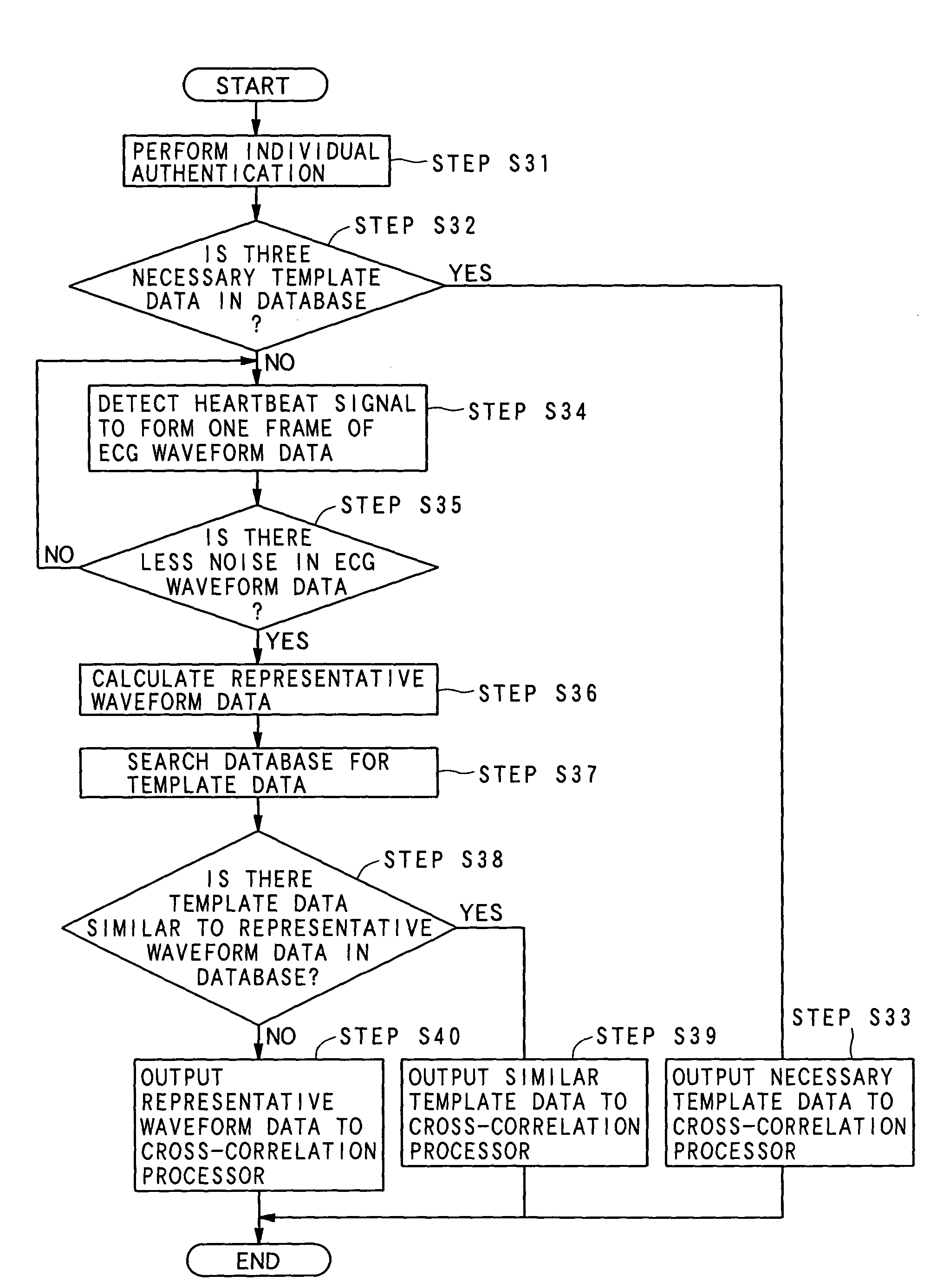
[0014]According to the present invention, it is possible to not only adequately enhance the peaks in the electrocardiogram waveform data produced from the heartbeat signal acquired from a person to be examined but also, on an individual basis, optimize the data from which a heart rate is figured out. Hence, even when there is body motion during detection of a heartbeat signal from the human to be examined and / or there is contact resistance intervening in a detecting path of the heartbeat signal, noise caused in electrocardiogram waveform data can easily be removed from the data or greatly suppressed in the data, thereby providing a heart-rate measuring apparatus with higher detection accuracy.
[0041]According to the present invention, it is possible to not only adequately enhance the peaks in the electrocardiogram waveform data produced from the heartbeat signal acquired from a person to be examined but also, on an individual basis, optimize the data from which a heart rate is figured out. Hence, even when there is body motion during detection of a heartbeat signal from the human to be examined and / or there is contact resistance intervening in a detecting path of the heartbeat signal, noise caused in electrocardiogram waveform data can easily be removed from the data or greatly suppressed in the data, thereby providing a heart-rate measuring apparatus with higher detection accuracy.

Problems solved by technology

However, the above conventional electrocardiogram analysis apparatus has suffered from the problem that error in the detection of R waves from the electrocardiogram waveform is obliged to be larger.
Insufficient noise removal from the heart rate signal will spoil an accurate production of electrocardiogram waveform data.
In particular, the foregoing conventional electrocardiogram analysis apparatus has a poor performance in removing noise from the detected heart rate signal, because the pattern matching carried out in the conventional electrocardiogram analysis apparatus is not necessarily effective.
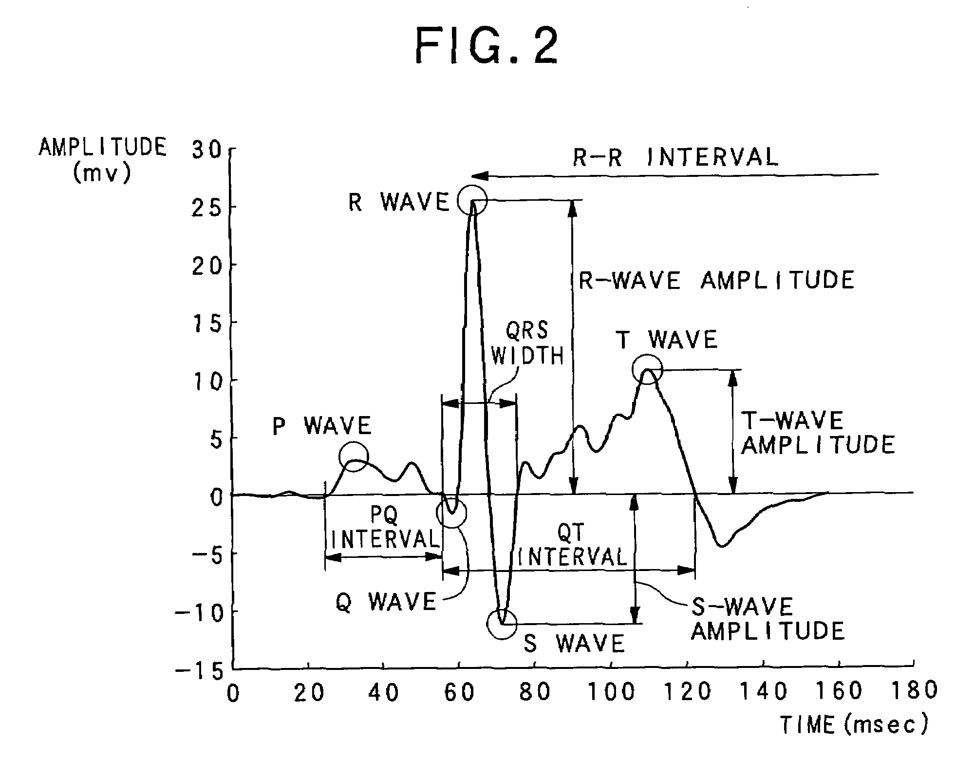
However, the electrocardiogram waveform elements, such as PQ interval, QT interval, and T-wave amplitude, have large influence resulting from individual differences, thus being apt to an erroneous detection of the R waves.

Method used


Image

  • System, method, program, and medium for measuring heart rate
  • System, method, program, and medium for measuring heart rate
  • System, method, program, and medium for measuring heart rate

Examples


first embodiment

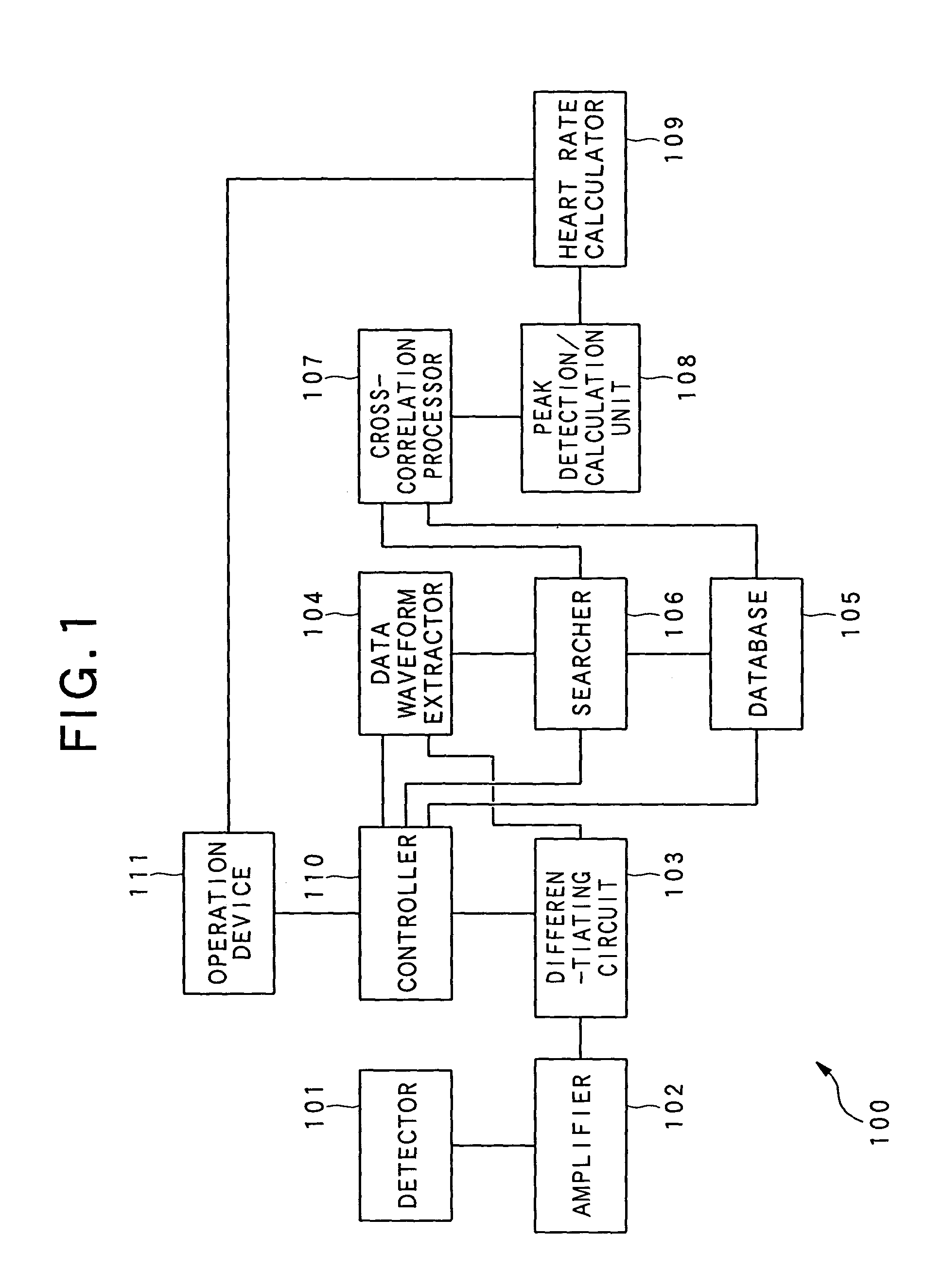
[0063]Referring to FIGS. 1 to 9, a first embodiment of the heart-rate measuring apparatus will now be described. First of all, FIG. 1 is used to explain the configuration of the heart-rate measuring apparatus according to this embodiment.

[0064]FIG. 1 shows the configuration of a heart-rate measuring apparatus 100 according to this embodiment.

[0065]In the present embodiment, as shown in FIG. 1, the heart-rate measuring apparatus 100 is provided with a detector 101 detecting a heartbeat signal from an object (human body); an amplifier 102 producing electrocardiogram waveform data based on the detected heartbeat signal; a differentiating circuit 103 removing lower-frequency components from the produced electrocardiogram waveform data; a data waveform extractor 104 extracting a single representative waveform data from the produced electrocardiogram waveform data; a database 105 in which a plurality of template data (described later) is stored in advance; a searcher 106 searching the dat...

second embodiment

[0172]Referring to FIG. 10, a second embodiment of the heart-rate measuring apparatus according to the present application will now be described.

[0173]FIG. 10 shows the configuration of the heart-rate measuring apparatus used in this embodiment.

[0174]The present embodiment has a feature of using a pulse-wave detector 201 in the configuration shown in the first embodiment, instead of the detector to detect a heartbeat signal at a leg, arm or chest portion of the human body. The pulse-wave detector will detect a heartbeat signal through measuring the pulse wave generated at a portion of the human body. The remaining components and the heart-rate measurement operations are identical or similar to those in the first embodiment, so the identical components to those are referred by the same numerals and will be omitted from being described for the sake of a simplified explanation.

[0175]As shown in FIG. 10, a heart-rate measuring apparatus 200 according to the present embodiment is provide...

third embodiment

[0195]Referring to FIGS. 11 and 12, a third embodiment of the heart-rate measuring apparatus according to the present invention will now be described.

[0196]The present embodiment features the configuration of searching the database for specifying template data with the use of amounts that are characteristic of representative waveform data used as electrocardiogram waveform data. This configuration is carried out in the first embodiment, in place of the configuration in which names of persons to be examined are adopted as identification information and the database is searched for specifying template data by using a person's name.

[0197]In the present embodiment, the characteristic amounts in representative waveform data consist of an amount indicating an interval of time between the P and Q waves (hereinafter referred to as “PQ interval”), a “QRS width”, and an amount indicating an interval of time between the Q and T waves (hereinafter referred to as “QT interval”).

[0198]These amoun...


PUM


Abstract

A heart-rate measuring apparatus is provided a database, acquisition unit, production unit, search unit, cross-correlation processing unit, and calculation unit. In the database, one or more sets of electrocardiogram (ECG) waveform data, serving as reference waveform data, of persons being examined are stored in advance. The acquisition unit acquires a heartbeat signal from a person being examined. The production unit produces ECG waveform data based on the acquired heartbeat signal. On the basis of the produced ECG waveform data, the search unit searches the database for reference waveform data of the person. The cross-correlation processing unit performs cross-correlation processing between the produced ECG waveform data and the searched reference waveform data, and the calculation unit calculates the heart rate based on the cross-correlated ECG waveform data using values of R-R intervals of the waveform.

Description

BACKGROUND OF THE INVENTION[0001]1. Field of the Invention[0002]The present invention relates to a method and system for measuring a heart rate of an object, such as a person to be examined, on the basis of a heartbeat signal acquired from the object.[0003]2. Description of the Related Art[0004]In recent years, applications of an electrocardiogram data indicative of the diastolic and systolic actions of the heart have been spread into various fields. Because it has been found that the influence of stress and fatigue caused in the human has come out as fluctuations in a heart rate or heart rate variability, the electrocardiogram data has been used in the field of human engineering and medical industry as well as the field of medical care, such as finding and diagnosis of cardiovascular diseases and monitoring medical conditions. Therefore, it is a recent demand to commercialize compact measurement apparatuses capable of measuring an amount of the heart rate and information in relatio...

Claims


Application Information

Patent Timeline
IPC IPC(8): A61B5/04A61B5/00A61B5/0245A61B5/352
CPCA61B5/0245A61B5/04525A61B5/0006A61B5/0456A61B5/7239A61B5/35A61B5/352
Inventor YASUSHI, MITSUOYANAGIDAIRA, MASATOSHI
Owner PIONEER CORP
Learn More