
ECG device

a monitoring device and electrocardiograph technology, applied in the field of portable electrocardiographs, can solve the problems of expensive equipment, cumbersome devices that only have a few hours' power, and are reluctant to wear the device for the necessary long periods, and achieve the effect of reliable and robustness

Active Publication Date: 2019-06-20
CAMBRIDGE HEARTWEAR LTD
View PDF5 Cites 1 Cited by
  • Summary
  • Abstract
  • Description
  • Claims
  • Application Information

AI Technical Summary

Benefits of technology

The present invention is a portable ECG device that can measure potential differences from three different anatomically significant locations near the heart simultaneously. This results in three independent ECG waveforms that maximize the potential output of the device. By optimizing each measurement, the device can detect abnormalities in heart conditions with higher sensitivity and specificity. The device is over-molded and sealed by an encapsulating material, making it robust and reliable for any conditions. Additionally, the device can filter noise to signal ratios, ensuring accurate data. The technical effect of this patent is the ability of the device to measure potential differences from multiple locations near the heart, resulting in more accurate and sensitive data for abnormalities underlying heart rhythms.

Problems solved by technology

This requires fixing 12 leads on to the patient's chest and carrying around this cumbersome device that only has a few hours' power.
The data is provided from the Holter monitor but due to the uncomfortable and non-ergonomic design, the patients are reluctant to wear the device for the necessary long periods to identify any intermittent or transient pathologies.
Furthermore, it is also a very expensive piece of equipment.
In addition, the data generated by the Holter monitor are not accessible in real time to provide a diagnosis.

Method used


Image

  • ECG device
  • ECG device
  • ECG device

Examples


Embodiment Construction

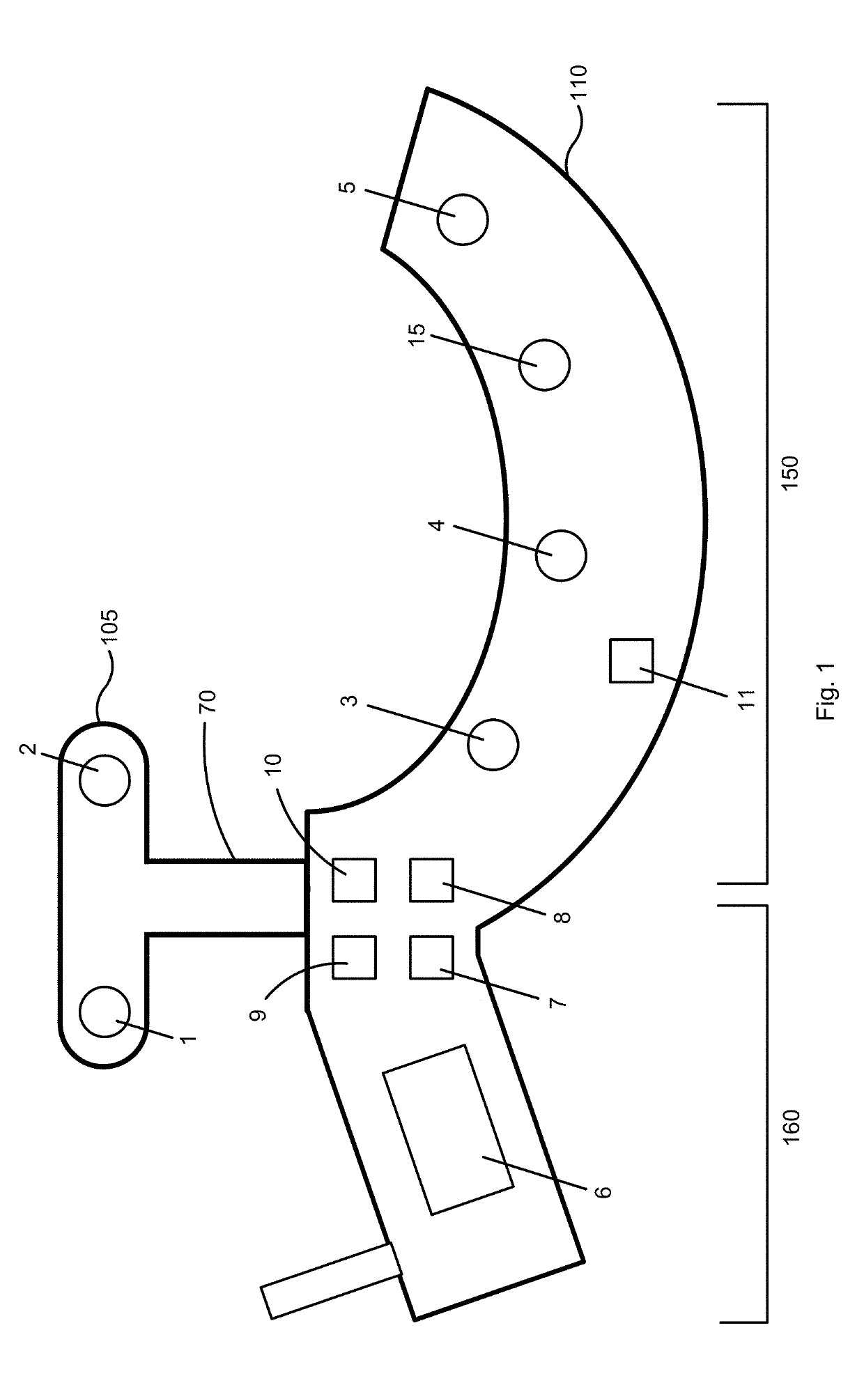
[0037]Some preferred embodiments of the disclosure will now be described by way of example only and with reference to the accompanying drawings, in which:

[0038]FIG. 1 illustrates a schematic representation of an exemplary ECG device according to one embodiment of the present disclosure;

[0039]FIG. 2 illustrates a schematic representation of three independent measurements according to one embodiment of the present disclosure;

[0040]FIG. 3 illustrates the ECG waveforms generated from the three independent measurements of FIG. 2;

[0041]FIG. 4 illustrates a schematic representation of the arrangements of the detectors according to one example of the present disclosure;

[0042]FIG. 5 illustrates a schematic assembled view of the ECG device according to one embodiment of the present disclosure;

[0043]FIG. 6(a) illustrates a schematic front view of an assembled ECG device according to one embodiment of the present disclosure; and

[0044]FIG. 6 (b) illustrates a schematic rear view of the assembled...


PUM


Abstract

We disclose a portable wearable device for measuring electrocardiographic signals, the device comprising a first portion comprising at least two electrodes; a second portion comprising at least three electrodes; the first portion and the second portion being vertically spaced from one another; a controller configured to take: a first potential difference measurement using one of the electrodes of the first portion and one of the electrodes of the second portion; a second potential difference measurement using one other of the electrodes of the first portion and one other of the electrodes of the second portion; and a third potential difference measurement using one other of the electrodes of the first portion and one other of the electrodes of the second portion. The controller is configured to simultaneously take the first, second and third potential difference measurements at three independent positions of a user's body.

Description

TECHNICAL FIELD OF THE DISCLOSURE[0001]The disclosure relates to a portable electrocardiograph (ECG) monitoring device.BACKGROUND OF THE DISCLOSURE[0002]Electrocardiograph (ECG) monitors are widely used to obtain medical (i.e. biopotential) signals containing information indicative of the electrical activity associated with the heart and any underlying pathology. To obtain medical signals, ECG electrodes are applied to the skin of a patient in various locations. The electrodes, after being positioned on the patient, connect to an ECG monitor by a set of ECG lead wires. The distal end of the ECG lead wire, or portion closest to the patient, may include a connector which is adapted to operably connect to the electrode to receive medical signals from the body. The proximal end of the ECG lead set is operably coupled to the ECG monitor and supplies the medical signals received from the body to the ECG monitor.[0003]Generally speaking, if we want to take an ECG as someone is going about ...

Claims


Application Information

Patent Timeline
Patent Type & Authority Applications(United States)
IPC IPC(8): A61B5/0408A61B5/0428A61B5/145B23P19/04A61B5/308
CPCA61B5/0408A61B5/0428A61B5/14542B23P19/04A61B2562/0271A61B2562/0219A61B5/6831A61B5/6823A61B2560/0425A61B2562/04A61B5/282A61B5/349A61B5/25A61B5/30A61B5/318
Inventor SHAKUR, RAMEEN
Owner CAMBRIDGE HEARTWEAR LTD
Learn More