
Aromatic compounds and organic electroluminescent devices made by using the same

Inactive Publication Date: 2007-06-26
GASOLINEEUM ENERGY CENT FOUND +1
View PDF8 Cites 2 Cited by
  • Summary
  • Abstract
  • Description
  • Claims
  • Application Information

AI Technical Summary

Benefits of technology

[0025]It is preferable that the organic compound layer comprises 1 to 70% by weight of the aromatic compound represented by general formula (I). When the content is smaller than 1% by weight, the effect of the invention cannot be obtained. When the content exceeds 70% by weight, the durability and the efficiency of light emission tend to decrease.
[0026]Where necessary, the light emitting layer or the organic compound layer may further comprise conventional light emitting materials, other doping materials, hole injection materials and electron injection materials in combination with the compound represented by general formula (I) of the present invention. By using a multi-layer structure for the organic EL device, decreases in the luminance and the lifetime due to quenching can be prevented. Using other doping materials, the luminance of emitted light and the efficiency of light emission can be improved, and emission of red light or white light can be obtained. By using other doping materials contributing to the light emission of the phosphorescence in combination, the luminance of emitted light and the efficiency of light emission can be improved.
[0027]The hole injection layer, the light emitting layer and the electron injection layer may each have a multi-layer structure. When the hole injection layer has a multi-layer structure, the layer into which holes are injected from the electrode is called the hole injection layer, and the layer which receives holes from the hole injection layer and transports holes to the light emitting layer is called the hole transport layer. Similarly, when the electron injection layer has a multi-layer structure, the layer into which electron are injected from the electrode is called the electron injection layer, and the layer which receives electrons from the electron injection layer and transports electrons to the light emitting layer is called the electron transport layer. The layers are selected in accordance with energy levels of the material, heat resistance and adhesion with the organic thin film layers or the metal electrodes.
[0028]Examples of the light emitting material and the host material which can be used for the organic compound layer in combination with the compound represented by general formula (I) include anthracene, naphthalene, phenanthrene, pyrene, tetracene, coronene, chrysene, fluoresceine, perylene, phthaloperylene, naphthaloperylene, perynone, phthaloperynone, naphthaloperynone, diphenylbutadiene, tetrapheny-butadiene, coumarine, oxadiazole, aldazine, bis-benzoxazoline, bis-styryl, pyrazine, cyclopentadiene, metal complexes of quinoline, metal complexes of aminoquinoline, metal complexes of benzoquinoline, imines, diphenylethylene, vinylanthracene, diaminocarbazole, pyrane, thiopyrane, polymethine, melocyanine, oxinoid compounds chelated with imidazole, quinacridone, rubrene, stilbene-based derivatives and fluorescence pigments.
[0029]As the hole injection material, compounds which have the ability to transport holes, exhibits the excellent effect of receiving holes injected from the anode and the excellent effect of injecting holes to the light emitting layer or the light emitting material, prevents transfer of excitons formed in the light emitting layer to the electron injection layer or the electron injection material and has the excellent ability of forming a thin film, are preferable. Examples of the hole injection compound include phthalocyanine derivatives, naphthalocyanine derivatives, porphyrin derivatives, oxazoles, oxadiazoles, triazoles, imidazoles, imidazolones, imidazolethiones, pyrazolines, pyrazolones, tetrahydroimidazoles, oxazoles, oxadiazoles, hydrazones, acylhydrazones, polyarylalkanes, stilbene, butadiene, triphenylamine of the benzidine type, triphenylamine of the styrylamine type, triphenylamine of the diamine type, derivatives of the above compounds and macromolecular materials such as polyvinyl-carbazoles, polysilanes and electrically conductive macromolecules.
[0030]Among these hole injection materials, the more effective hole injection materials are aromatic tertiary amine derivatives and phthalocyanine derivatives. Examples of the aromatic tertiary amine derivative include triphenylamine, tritolylamine, tolyldiphenylamine, N,N′-diphenyl-N,N′-(3-methylphenyl)-1,1′-biphenyl-4,4′-diamine, N,N,N′,N′-(4-methylphenyl)-1,1′-phenyl-4,4′-diamine, N,N,N′,N′-(4-methyl-phenyl)-1,1′-biphenyl-4,4′-diamine, N,N′-diphenyl-N,N′-dinaphthyl-1,1′-biphenyl-4,4′-diamine, N,N′-(methylphenyl)-N,N′-(4-n-butylphenyl)-phenanthrene-9,10-diamine, N,N-bis(4-di-4-tolylaminophenyl)-4-phenyl-cyclohexane and oligomers and polymers having the skeleton structure of these aromatic tertiary amines. Examples of the phthalocyanine (Pc) derivative include phthalocyanine derivatives and naphthalocyanine derivatives such as H2Pc, CuPc, CoPc, NiPc, ZnPc, PdPc, FePc, MnPc, ClAlPc, ClGaPc, ClInPc, ClSnPc, Cl2SiPc, (HO)AlPc, (HO)GaPc, VOPc, TiOPc, MoOPc and GaPc-O—GaPc.

Problems solved by technology

Although this device exhibits an excellent purity of red light, the device requires an applied voltage as great as 11 V and has an insufficient half luminance lifetime of about 150 hours.
However, this device exhibits an insufficient purity of red light.
However, the color of the emitted light is reddish orange, and the chromaticity is insufficient.

Method used


Image

  • Aromatic compounds and organic electroluminescent devices made by using the same
  • Aromatic compounds and organic electroluminescent devices made by using the same
  • Aromatic compounds and organic electroluminescent devices made by using the same

Examples


preparation example 1

Synthesis of Compounds (101) and (101′)

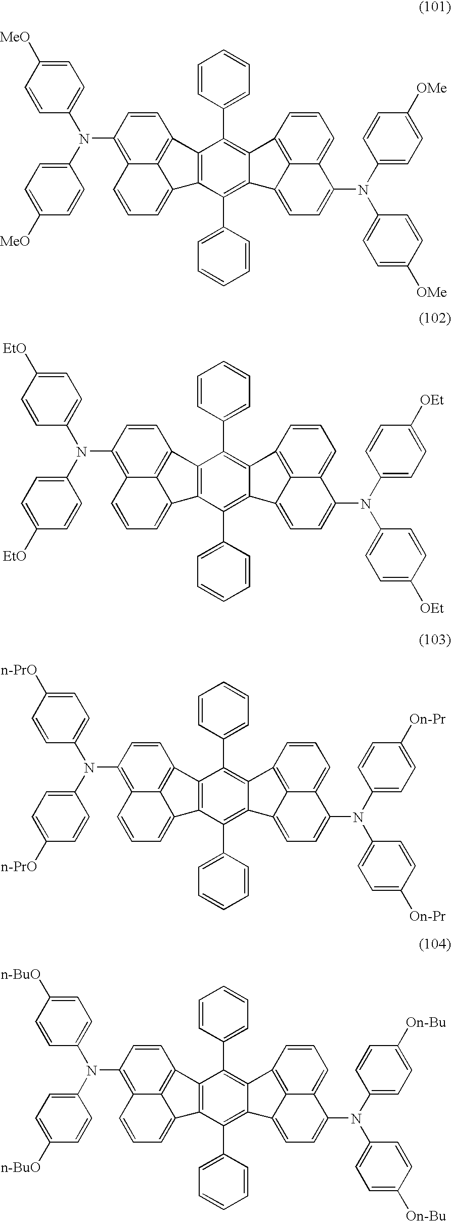
[0044]The equation exhibiting the chemical reaction in the route of synthesis of Compounds (101) and (101′) is shown in the following.

[0045]

[0046]Into a 100 ml three-necked flask, 3.0 g (4.72 mmol) of a mixture of 3,10-dibromo-7,14-diphenylacenaphtho[1.2-k]fluoranthene and 3,11-dibromo-7,14-diphenylacenaphtho[1.2-k]fluoranthene (the ratio of the amounts: 7:3), 2.38 g (10.38 mmol) of 4,4′-dimethoxydiphenylamine, 64 mg (0.07 mmol) of tris(dibenzylideneacetone)dipalladium(0), 88 mg (0.14 mmol) of (S)-(−)-BINAP (2,2′-bis(diphenylphosphino)-1,1′-binaphthyl) and 1.1 g (11.4 mmol) of sodium t-butoxide were placed. After the flask was purged with argon, 50 ml of dehydrated toluene was added. The temperature of the resultant mixture was elevated to 110° C. under stirring, and the mixture was stirred further for 7 hours. After the reaction was completed, the reaction mixture was cooled to the room temperature, and 50 ml of dichloromethane was added. Afte...

preparation example 2

Synthesis of Compounds (108) and (108′)

[0049]The equation exhibiting the chemical reaction in the route of synthesis of Compounds (108) and (108′) is shown in the following.

[0050]

[0051]Into a 100 ml three-necked flask, 3.0 g (4.72 mmol) of a mixture of 3,10-dibromo-7,14-diphenylacenaphtho[1.2-k]fluoranthene and 3,11-dibromo-7,14-diphenylacenaphtho[1.2-k]fluoranthene (the ratio of the amounts: 9:1), 2.21 g (10.38 mmol) of (4-methoxyphenyl)-p-tolylamine, 64 mg (0.07 mmol) of tris(dibenzylideneacetone)dipalladium(0), 88 mg (0.14 mmol) of (S)-(−)-BINAP and 1.1 g (11.4 mmol) of sodium t-butoxide were placed. After the flask was purged with argon, 50 ml of toluene was added. The temperature of the resultant mixture was elevated to 110° C. under stirring, and the mixture was stirred further for 7 hours. After the reaction was completed, the reaction mixture was cooled to the room temperature, and 50 ml of dehydrated toluene was added. After being stirred at the room temperature for some ti...

preparation example 3

Synthesis of Compounds (504) and (504′)

[0054]The equation exhibiting the chemical reaction in the route of synthesis of Compounds (504) and (504′) is shown in the following.

[0055]

[0056]Into a 100 ml three-necked flask, 2.0 g (3.15 mmol) of a mixture of 3,10-dibromo-7,14-diphenylacenaphtho[1.2-k]fluoranthene and 3,11-dibromo-7,14-diphenylacenaphtho[1.2-k]fluoranthene (the ratio of the amounts: 8:2), 1.80 g (7.99 mmol) of (4-isopropylphenyl)-p-tolylamine, 44 mg (0.047 mmol) of tris(dibenzylideneacetone)dipalladium(0), 59 mg (0.095 mmol) of (S)-(−)-BINAP and 848 mg (8.82 mmol) of sodium t-butoxide were placed. After the flask was purged with argon, 50 ml of dehydrated toluene was added. The temperature of the resultant mixture was elevated to 115° C. under stirring, and the mixture was stirred further for 7.5 hours. After the reaction was completed, the reaction mixture was cooled to the room temperature, and 50 ml of dichloromethane was added. After being stirred at the room temperatu...


PUM

PropertyMeasurementUnit
Percent by massaaaaaaaaaa
Weightaaaaaaaaaa
Purityaaaaaaaaaa

Abstract

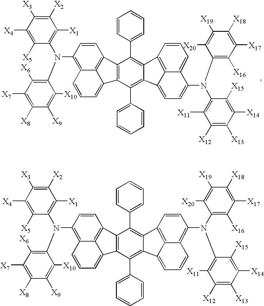
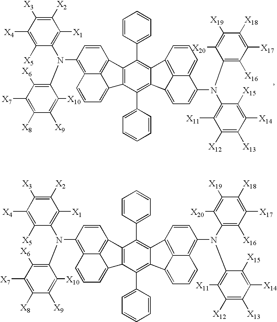
A novel aromatic compound represented by following general formula (I):among X1 to X20 in general formula (I), (1) at least four each independently represent a linear or branched alkoxyl group having 1 to 6 carbon atoms, and others each represent hydrogen atom; (2) at least one represents a linear or branched alkyl group having 1 to 6 carbon atoms, at least one represents a linear or branched alkoxyl group having 1 to 6 carbon atoms, a total of a number of the alkyl group and a number of the alkoxyl group being 4 or greater, and others each represent hydrogen atom; (3) at least six each independently represent a linear or branched alkyl group having 1 to 6 carbon atoms, and others each represent hydrogen atom; or (4) at least four each independently represent a linear or branched alkyl group having 1 to 6 carbon atoms, two among said alkyl groups having 3 to 6 carbon atoms, and others each represent hydrogen atom; and an organic electroluminescence device using the aromatic compound, are provided. The device exhibits excellent purity of color, provides great luminance of emitted light and efficiency of light emission even at a small driving voltage, has a long lifetime and emits reddish light.

Description

TECHNICAL FIELD[0001]The present invention relates to a novel aromatic compound and an organic electroluminescence device using the compound and, more particularly, to an organic electroluminescence device which exhibits excellent purity of color, provides great luminance of emitted light and efficiency of light emission, has a long lifetime and emits reddish light and a novel aromatic compound utilized for the electroluminescence device.Background Art[0002]Organic electroluminescence (“electroluminescence” will be referred to as “EL”, hereinafter) devices which utilize organic substances are expected to be useful for application as an inexpensive full color display device of the solid light emission type having a great size, and various developments on the organic EL devices are being conducted. In general, an organic EL device has a construction comprising a light emitting layer and a pair of electrodes disposed at both sides of the light emitting layer. When an electric field is ...

Claims


Application Information

Patent Timeline
IPC IPC(8): H01J1/62C07C211/00H01L51/50C07C211/61C07C217/92C07C217/94C09K11/06H01L51/00H01L51/30H05B33/14H05B33/22
CPCC07C211/61C07C217/94C09K11/06H01L51/0056H01L51/006H05B33/14C07C2103/54C09K2211/1007C09K2211/1011C09K2211/1014H01L51/0055H01L51/5012H01L51/5048Y10S428/917C07C2603/54H10K85/623H10K85/624H10K85/633H10K50/14H10K50/11
Inventor IWAKUMA, TOSHIHIROARAKANE, TAKASHIKUSUMOTO, TADASHI
Owner GASOLINEEUM ENERGY CENT FOUND
Learn More