
Optimised alkaline electrochemical cells

a technology of alkaline electrochemical cells and alkaline electrochemicals, which is applied in the direction of primary cell electrodes, electrochemical generators, cell components, etc., can solve the problems of limiting the maximum amount of ingredients which can be put into any given cell, increasing the volume, and reducing so as to reduce the quantity of active materials and improve the performance. , the effect of small volum

Inactive Publication Date: 2007-06-19
ENERGIZER BRANDS
View PDF16 Cites 9 Cited by
  • Summary
  • Abstract
  • Description
  • Claims
  • Application Information

AI Technical Summary

Benefits of technology

[0071]The porosity of either electrode may be increased in any suitable manner. In the case of the anode, for example, this may be achieved by increasing the internal diameter of the cathode, thereby increasing the volume of the anode, while keeping the same amount of zinc. If the volume of the anode is not increased, then the amount of zinc and, concomitantly, the amount of cathode material, must be reduced in order to reduce the anode porosity, unless a deliberate decision is taken to vary the A:C ratio. It will be appreciated that it is an advantage of the present invention that the overall amount of active electrode material can be reduced while increasing cell performance.
[0072]The zinc used in the anode must be properly selected to maintain sufficient electrical conductivity within the anode. The zinc must include particles that have shapes and sizes that will do so even though the amount of zinc relative to the anode is relatively small. Zinc containing particles that are able to maintain the conductive matrix at lower concentrations has a relatively low tap density. Above a porosity of about 66%, the anode preferably comprises non-granular zinc. Such zinc may simply be any form with greater surface area than normal powdered zinc used in cells.
[0073]Preferably the overall tap density of the zinc used in cells made according to the present invention, with an anode porosity equal to or greater than 69%, is less than 3.2 g / cc. In general, as the anode porosity is increased, the tap density of the zinc must be reduced. For lower porosity anodes, the preferred maximum tap density is lower, by 0.06 g / cc for every 1% increase in anode porosity above 69%. It is more preferred that when the anode porosity is 69% the overall tap density of the zinc is no greater than 3.13 g / cc, and for lower porosity anodes the overall tap density is 0.085 g / cc lower for every 1% increase in anode porosity above 69%. When the anode porosity is about 71%, the preferred overall tap density of the zinc is from 2.83 to 2.96 g / cc, inclusive.
[0074]One way to control the overall tap density is to use a mixture of high and low density zincs. For example, conventional, irregularly shaped, high-density zinc powder may be blended with uniformly shaped, low-density zinc particles to obtain the desired overall tap density. Such mixtures may also have processing or cost advantages.
[0075]“Uniformly shaped zinc particles” means that the individual particles of zinc have substantially consistent morphology. This is in contrast with typical zinc powders with consistently irregular shapes, few of which are similar to each other. To have a uniform shape, each of the particles' shape factor must be substantially similar to all other particles. Therefore, for example, if the uniform shape is flakes, then all of the particles must be flakes. In order to produce uniformly shaped particles, control of the forming or classification process should be used to ensure the desired consistent particle shape. The shapes of zinc particles can be determined by examining the particles with a scanning electron microscope.
[0076]The overall tap density of the zinc is calculated from the measured tap densities of the different types of zinc contained in the anode. The overall tap density equals 100 / Σ(dn / wn), where dn is the tap density of zinc type n and wn is the weight percent of zinc type n, based on the total amount of zinc particles in the anode. If a single zinc type is used, the overall tap density is equal to the measured tap density of a sample of that zinc.

Problems solved by technology

The competition to produce the best alkaline battery continues to be fierce, but a large number of restrictions exist, not least of which is the size of any given cell.
Thus, whichever battery is chosen must fit within a given volume, thereby limiting the maximum amount of ingredients which it is possible to put into any given cell.
When it becomes impractical to further increase the volume of the cell ingredients, battery manufacturers then have the problem of trying to further enhance performance and battery life through enhancing and / or changing the ingredients used, but there must, ultimately, be a limit.
However, the use of CMD is not desirable in all cases, since CMD has both a lower peroxidation and a lower density than electrolytic manganese dioxide (EMD).
The drawbacks to this construction include the fact that there is a substantially reduced capacity in the cell and that the MnO2:C ratio is very low but, more importantly, that this cathode material becomes very difficult to handle, so that it is impractical to make a cell containing such material using conventional manufacturing processes and equipment.
The capacity and performance of such cells is also severely compromised by comparison with US '139.
Such porosities tend to separate zinc particles and increase impedance, especially in a 1-meter drop test.
In alkaline batteries, the use of voltage boosting agents such as Ag2O and ferrates is theoretically attractive, but cost, handling, and instability can be problems.
Efforts to increase the electrical conductivity of the anode and cathode as a means of improving discharge performance at high constant wattage have met with little or no success, as the necessary changes in other parameters has counteracted the improvements.
It is well known that dry cell batteries were originally made with mercury, but concern about potential damage to the environment caused by the disposal of large amounts of mercury-containing batteries was substantial.
Removing mercury made the anodic zinc electronically inefficient, and the quantity of zinc had to be increased.
However, the function of the excess zinc is that of a conductor, not an active material, so it limits the amounts of active material that can be put into the battery.
An additional disadvantage is that any zinc left after the cell has been exhausted can react with any remaining water to create hydrogen.
However, reducing the quantity of graphite reduces the active centres for conducting the second reaction, so that the second electron reaction becomes inefficient.
This effect leads to leakage following deep discharge.

Method used


Image

  • Optimised alkaline electrochemical cells
  • Optimised alkaline electrochemical cells
  • Optimised alkaline electrochemical cells

Examples


example 1

[0193]Table 2 summarises key cell features as well as the discharge duration in minutes on the 1 A cont. test to 1.0 V (in column “1A”).

[0194]

TABLE 2CathodeInitialAnodePorosityIDKOHFlakePorosityCathodeAnode(%)AhEMD:C(mm)(wt %)Separator(wt %)(%)1AEff %Eff %>272.6–2.970–7628.82.9308.85381 × VLZ / AA:SS370.75632.024.031.32.8268.85401 × VLZ / AA:SS572.25633.325.131.32.7239.05402 × VLZ105571.75534.325.831.32.7239.05401 × VLZ / AA:SS874.35433.725.333.82.7238.85402 × VLZ105370.35534.525.933.82.7238.58401 × VLZ / AA:SS773.45635.126.433.82.6239.05412 × VLZ105672.85535.826.933.82.6239.05411 × VLZ / AA:SS1075.55435.226.436.32.7208.58401 × VLZ / AA:SS572.25434.025.5>272.4–2.6>7628.82.6269.40401 × VLZ / AA:SS1276.75132.724.631.32.5269.40411 × VLZ / AA:SS1377.75134.025.633.82.4238.85421 × VLZ / AA:SS1578.85034.726.12.6–2.970–7625.82.9309.05401 × VLZ / AA:SS572.25330.522.922.32.8269.40391 × VLZ / AA:SS1075.34929.221.925.82.8209.05391 × VLZ / AA:SS673.05231.023.325.82.7209.40401 × VLZ / AA:SS1377.25232.124.126.92.8269.16401...

example 2

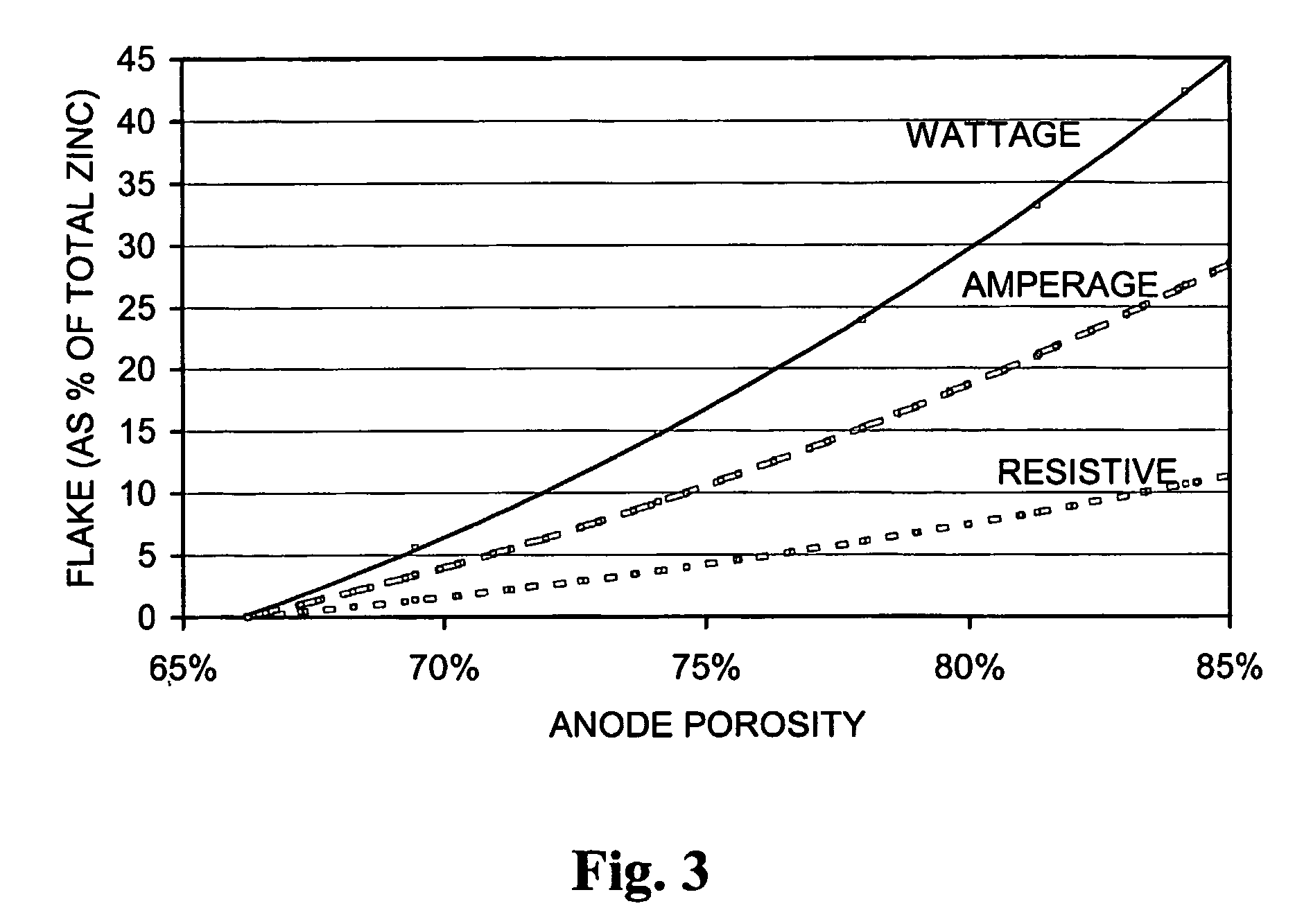
[0201]Table 3 to illustrates the effect of increasing the level of zinc flake. The data from the first region in Table 2 is repeated in the second region of Table 3 for ease of comparison.

[0202]

TABLE 3CathodeInitialAnodePoros.KOHFlakePorosityCathAnode(%)AhEMD:CID(wt %)Separator(wt %)(%)1AEff %Eff %>272.6–2.970–7628.82.9308.85381 × VLZ / AA:SS570.75933.7%25.3%32.62.9258.65391 × VLZ / AA:SS570.75934.4%25.9%33.82.8238.58391 × VLZ / AA:SS570.36035.8%26.9%33.82.8238.58391 × VLZ / AA:SS870.35935.2%26.5%36.32.7208.58401 × VLZ / AA:SS871.85836.5%27.4%>272.6–2.970–7628.82.9308.85381 × VLZ / AA:SS370.75632.024.031.32.8268.85401 × VLZ / AA:SS572.25633.325.131.32.7239.05402 × VLZ105571.75534.325.831.32.7239.05401 × VLZ / AA:SS874.35433.725.333.82.7238.85402 × VLZ105370.35534.525.933.82.7238.58401 × VLZ / AA:SS773.45635.126.433.82.6239.05412 × VLZ105672.85535.826.933.82.6239.05411 × VLZ / AA:SS1075.55435.226.436.32.7208.58401 × VLZ / AA:SS572.25434.025.5

[0203]Table 3 shows that increasing the flake level slightly ser...

example 3

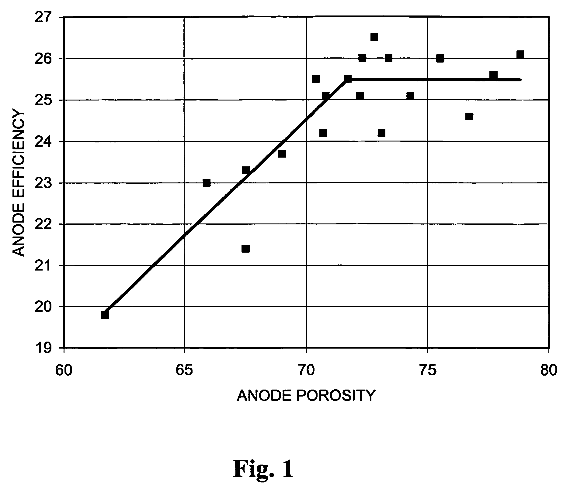
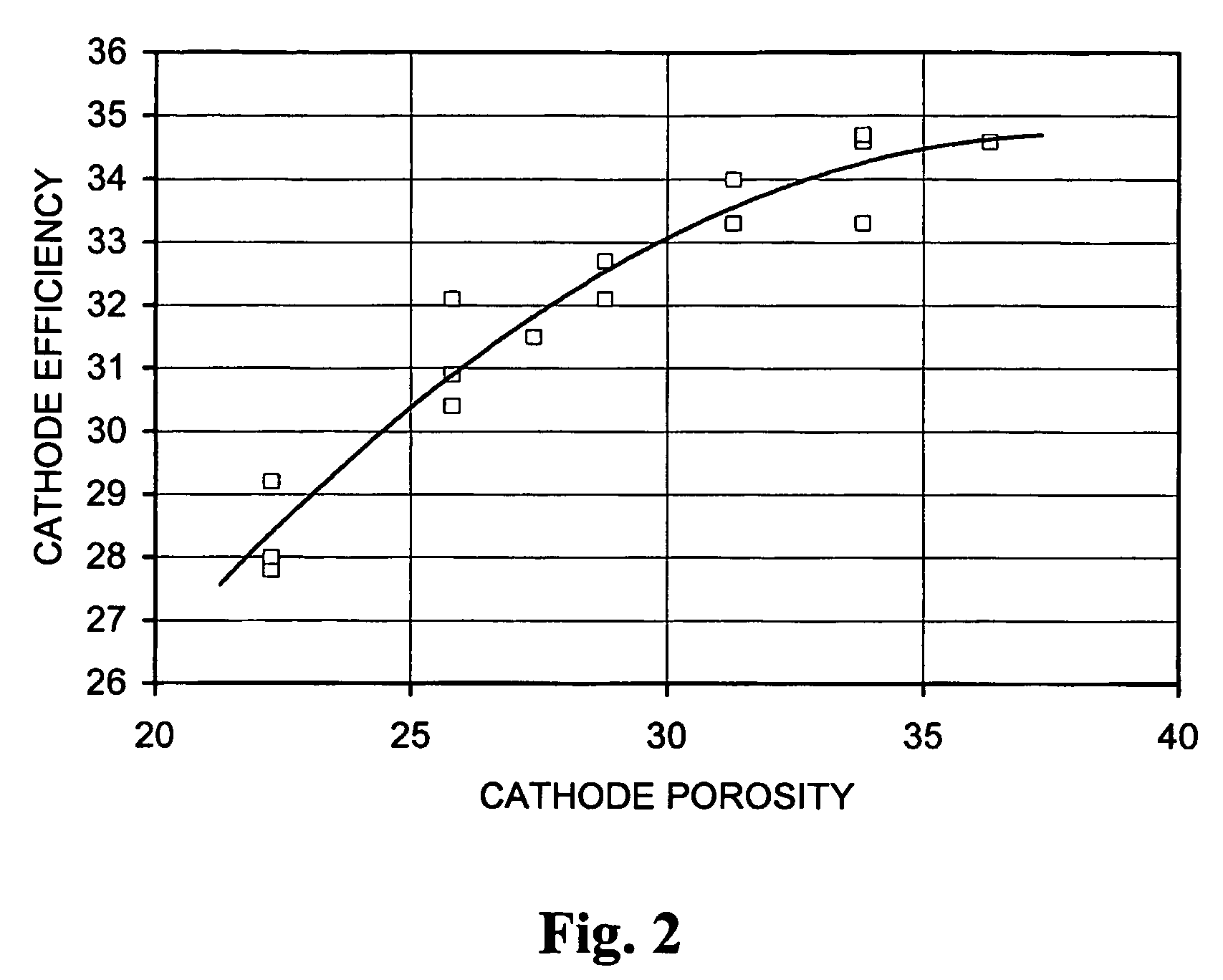
[0204]Accompanying FIG. 1 illustrates the effect of anode porosity on anode efficiency on 1 Amp continuous discharge to 1.0 V (cathode porosity above 28%), while FIG. 2 illustrates the effect of cathode porosity on cathode efficiency on 1 Amp continuous discharge to 1.0 V (anode porosity about 70–71%). It can clearly be seen that anode efficiency plateaus substantially at an anode porosity of around 71%. Cathode efficiency continues to rise above 28% but, as illustrated above, is counteracted by loss in capacity.


PUM


Abstract

Alkaline electrochemical cells with substantially increased performance characteristics have a porous anode, with a porosity equal to or greater than 69%, and a porous cathode, comprising manganese dioxide and having a porosity equal to or greater than 26%.

Description

BACKGROUND OF THE INVENTION[0001]The present invention relates to alkaline electrochemical cells having porous cathodes comprising manganese dioxide.[0002]Alkaline electrochemical cells have been commercially available for well over twenty years. In many modern applications, alkaline cells vastly outperform traditional zinc carbon cells, and are the batteries of choice for most consumers.[0003]The competition to produce the best alkaline battery continues to be fierce, but a large number of restrictions exist, not least of which is the size of any given cell.[0004]Conventional sizes for primary alkaline batteries include AAA, AA, C, D and 9V (LR03, LR6, LR14, LR20 and 6LR61, respectively), and standard dimensions are laid down for all of these types. Thus, whichever battery is chosen must fit within a given volume, thereby limiting the maximum amount of ingredients which it is possible to put into any given cell.[0005]Working against these constraints, battery manufacturers have, fo...

Claims


Application Information

Patent Timeline
IPC IPC(8): H01M4/50H01M10/26H01M4/42H01M4/62H01M4/02H01M4/06H01M6/06
CPCH01M4/50H01M6/045H01M4/625H01M2004/021
Inventor RANDELL, CHRISTOPHER F.
Owner ENERGIZER BRANDS
Learn More