
Estimating the operating point on a non-linear traveling wave tube amplifier

a traveling wave tube amplifier and operating point technology, applied in the field of system and method for transmitting data, can solve the problems of limited electromagnetic spectrum availability, difficult to implement either improvement in old systems or new services, and inability to simply transmit enhanced or additional data at a new frequency, etc., to achieve the effect of simplifying the reconstruction of the upper signal

Inactive Publication Date: 2007-06-12
DIRECTV LLC
View PDF168 Cites 9 Cited by
  • Summary
  • Abstract
  • Description
  • Claims
  • Application Information

AI Technical Summary

Benefits of technology

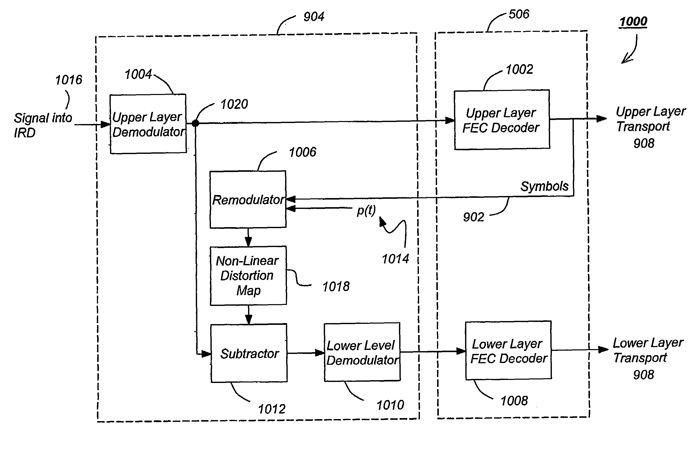
The present invention provides a method and apparatus for measuring and applying the non-linearity of a traveling wave tube amplifier (TWTA) in satellite communications involving layered modulation. This invention helps to accurately extract a lower-layer signal in a layered modulation scheme, minimizing the amount of power required for both layers of a signal and monitoring the health of the TWTA. The invention measures the non-linearity of the TWTA by determining the operating points for the TWTA, which can be used to reconstruct the upper layer signal more accurately. The measured non-linearity can be offset to simplify the reconstruction of the upper signal, and certain data may fall outside of the measured non-linearity, which can be interpolated using bounding points. The input operating point and output operating point can also be mapped to a particular level to avoid fractional overflow.

Problems solved by technology

However, it is more difficult to implement either improvement in old systems or new services when it is necessary to replace existing legacy hardware, such as transmitters and receivers.
In the realm of wireless communications, this principle is further highlighted by the limited availability of electromagnetic spectrum.
Thus, it is not possible (or at least not practical) to merely transmit enhanced or additional data at a new frequency.
Unfortunately, QPSK receivers cannot demodulate conventional 8PSK or 16QAM signals.
However, such an accurate reproduction and knowledge of the operating point presents a significant roadblock.
Errors in the estimation of the operating point can have a significant impact when reconstructing the upper layer-signal.
However, TWTA characteristics including the non-linearity and operating point may change over time (including after satellite launch).

Method used


Image

  • Estimating the operating point on a non-linear traveling wave tube amplifier
  • Estimating the operating point on a non-linear traveling wave tube amplifier
  • Estimating the operating point on a non-linear traveling wave tube amplifier

Examples


Embodiment Construction

[0049]In the following description, reference is made to the accompanying drawings which form a part hereof, and which is shown, by way of illustration, several embodiments of the present invention. It is understood that other embodiments may be utilized and structural changes may be made without departing from the scope of the present invention.

1. Overview

[0050]The invention provides a method of determining / estimating the operating point of a TWTA. The operating point is estimated at the same time TWTA non-linearity is measured. Therefore, no extra measurement procedures are required for the determination of the operating point, and the measured non-linearity is always up-to-date, allowing the measurement to follow any changes in TWTA characteristics over time.

2. Video Distribution System

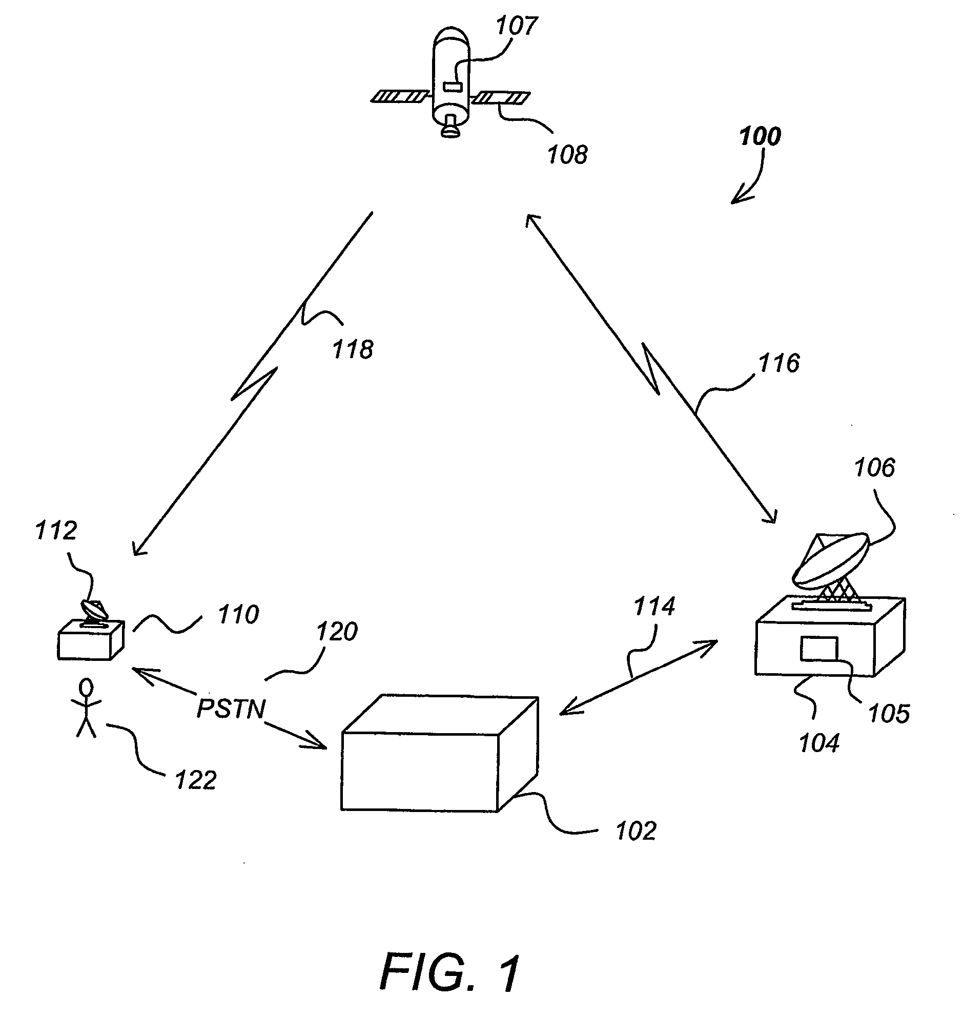
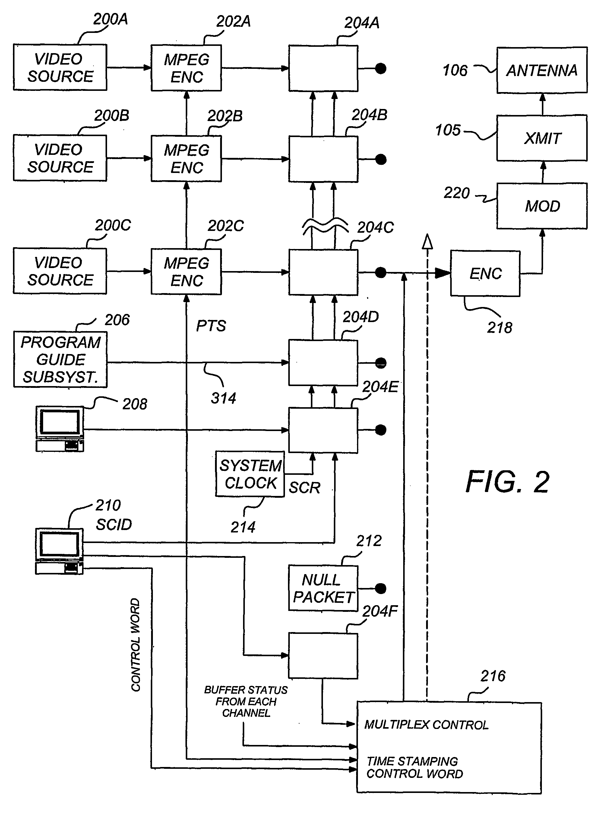
[0051]FIG. 1 is a diagram illustrating an overview of a single satellite video distribution system 100. The video distribution system 100 comprises a control center 102 in communication with an upl...


PUM


Abstract

A method, apparatus, article of manufacture, and a memory structure provide the ability to determine an input operating point and an output operating point on a non-linear traveling wave tube amplifier (TWTA). The non-linearity of the TWTA is measured. An input roots mean-square (RMS) value of an input signal used to measure the non-linearity of the TWTA is computed. The RMS value identifies an input operating point of the measured non-linearity of the TWTA. Lastly, an output operating point is obtained.

Description

CROSS-REFERENCE TO RELATED APPLICATIONS[0001]This application claims the benefit under 35 U.S.C. §119(e) of the following U.S. Provisional Patent Applications, which are incorporated by reference herein:[0002]U.S. Provisional Patent Application No. 60 / 421,289, filed Oct. 25, 2002 by Ernest C. Chen and Shamik Maitra, entitled “ESTIMATING THE OPERATING POINT ON A NONLINEAR TRAVELING WAVE TUBE AMPLIFIER”; and[0003]U.S. Provisional Patent Application No. 60 / 510,368, filed on Oct. 10, 2003, by Ernest C. Chen, entitled “IMPROVING TWTA AM-AM AND AM-PM MEASUREMENT”.[0004]This is a continuation-in-part application and claims the benefit under 35 U.S.C. §120 of the following co-pending and commonly-assigned U.S. utility patent applications, which are incorporated by reference herein:[0005]Utility application Ser. No. 09 / 844,401, filed Apr. 27, 2001, by Ernest C. Chen, entitled “LAYERED MODULATION FOR DIGITAL SIGNALS;” and[0006]U.S. application Ser. No. 10 / 165,710, filed on Jun. 7, 2002, by Er...

Claims


Application Information

Patent Timeline
Patent Type & Authority Patents(United States)
IPC IPC(8): H03F3/58H03FH04B1/04
CPCH01J25/49H04B1/0475H03F3/58
Inventor CHEN, ERNEST C.MAITRA, SHAMIK
Owner DIRECTV LLC
Learn More